How to Use Capacitors Safely
(Al-Ecap, MF-cap & MLCC)
Contents
Lifetime Estimation of Capacitors
As described in section 1.2, there are various types of capacitors and they are used in applications according to their features. Specifically, capacitors are selected to suit the features, quality, reliability, cost, space factor, and other requirements of the application. However, there are often trade-offs between requirements, such as capacitance and size, and capacitor selection and use should be considered well in advance. In this chapter, we explain how to select and use them, focusing on Al-Ecap and MF-cap that we offer*01.
*01 Our capacitors are used in power electronics devices that convert electrical energy into power or heat, or convert power into AC or DC.
Applications
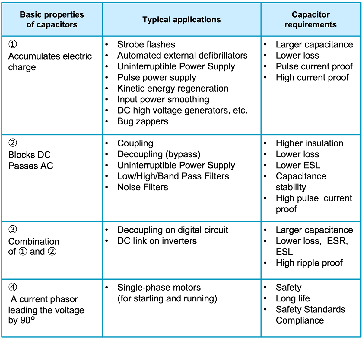
As shown in Table 4-01, As shown in Table 4-01, the actual circuit applies the basic properties of capacitors to enhance the performance of the circuit. Therefore, once a capacitor fails, not only is equipment performance degraded, but safety is also at risk. Capacitor failure and service life are directly related to equipment reliability.
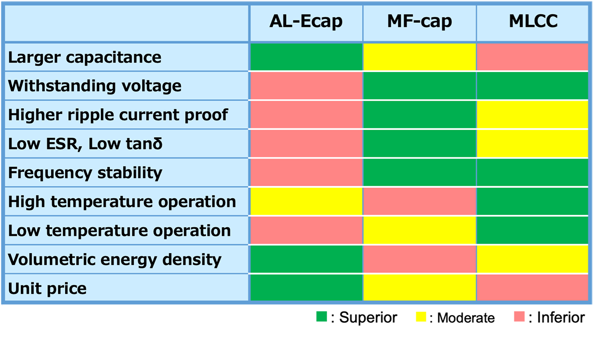
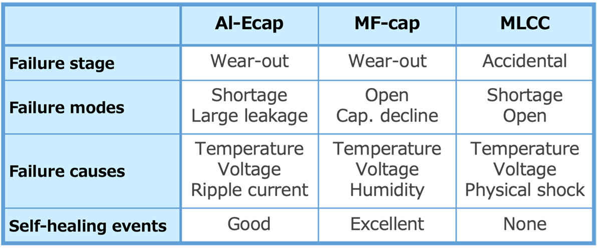
Al-Ecap and MF-cap are important and indispensable capacitors in power electronics, but the use of both is an interesting challenge. Consider, for example, the issue of whether Al-Ecap or MF-cap is more suitable for the DC link of an inverter: Al-Ecap has an expected lifetime of 8 to 10 years, and its main failure modes are short circuits and increased leakage current. However, Al-Ecap is less expensive than MF-cap, so it is still used in most inverters with periodic replacement based on life expectancy estimates. On the other hand, MF-caps have an expected lifetime of up to 15 to 20 years and can handle large ripple currents, with the main failure modes being opens and capacitance depletion. However, their large size, compared to Al-Ecap, means that they do not have an extensive track record of long-term use.
In selecting a capacitor, the advantages and disadvantages of each capacitor (Table 2) and the differences in failure modes (Table 3) should be fully considered. We are a specialized manufacturer of Al-Ecap and MF-cap, so please do not hesitate to contact us for help in selecting the right capacitor.
Design Margin and Derating
Derating in capacitors means using a capacitor at a voltage lower than its rated voltage or at a temperature lower than its rated temperature. Specifically, the use of a 100 V capacitor or operating a capacitor with a rated temperature of 105°C at an ambient temperature of 60°C is called derating. The reason for derating, is to ensure safety against voltage and temperature, which are major stresses for capacitors. In other words, proper derating not only extends lifetime, but also provides a safeguard against unexpected events such as sudden voltage spikes or changes in ambient temperature.
Capacitor ratings are specified by the manufacturer, and the ratings include a certain margin of reliability based on the manufacturer's respective design concepts. However, manufacturers do not guarantee long-term operation over decades. For this reason, manufacturers provide derating curves (Fig. 1) that show the relationship between applied voltage and ambient temperature, and recommend that capacitors be used within the range of the derating curves for higher reliability.*02
*02 MIL-HDBK-1547 shows various derating curves.
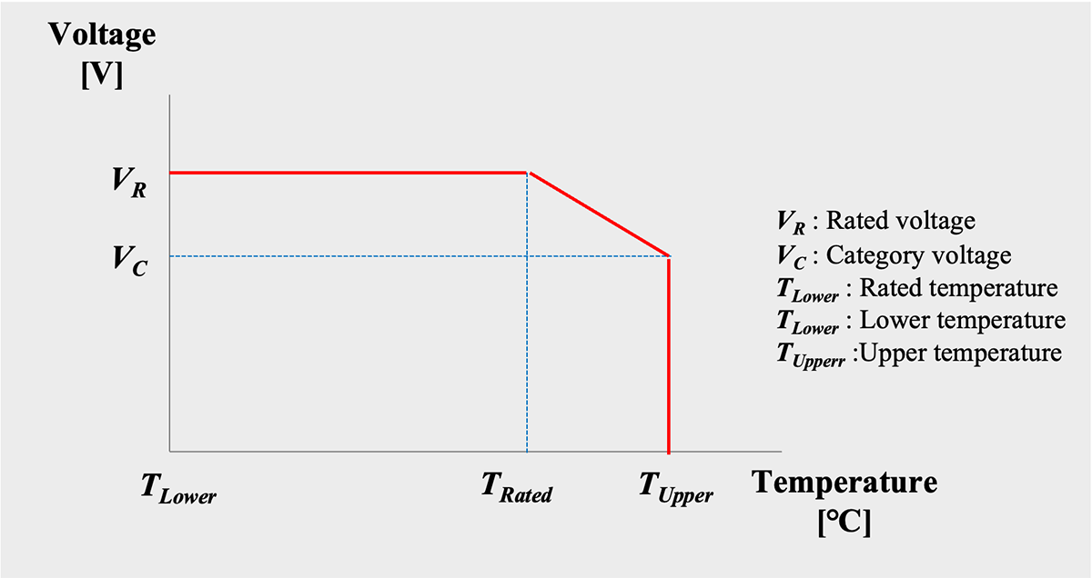
Schematic diagram of derating curve
Variations in Capacitor Characteristics
The characteristics of electronic components have variations, but the width and distribution of the variations vary depending on the type of component. For example, general-purpose carbon film resistors are adjusted to a specified resistance value by trimming the thin film after forming a thin film of carbon by vapor deposition or other methods. As a result, even for resistors with a nominal tolerance of ±5%, the actual resistance variation is within ±2%. Some diode products have the same rated current but different withstand voltage. For example, if rated at 400V, the withstand voltage is designed to be no lower than 400V, and the distribution extends to 1000V or higher. (The manufacturer guarantees that the withstand voltage will not be less than 400V.) Therefore, most 400V diodes are the same as 600V and 800V diodes.
The manufacturing process for capacitors does not involve the tuning like resistors. Capacitance is produced by controlling surface area and dielectric thickness. However, there is a trade-off between dielectric thickness and withstand voltage. Withstand voltage is associated with heavy fault failure in capacitors, so they are manufactured with priority given to dielectric thickness that can maintain withstand voltage.
The capacitance and tolerance apply the E series defined by the International Electrotechnical Commission (IEC) *03. E6 series (tolerance ±20%) and E12 series (±10%) are commonly used for Al-Ecap, and E6 series, E12 series (±10%), E24 series (±5%), E48 series (±2%) are commonly used. As shown in Fig.4-02, the larger the standard value, the wider the tolerance range, and it is important to understand that capacitance varies within the tolerance range.
*03 These standard values are published in IEC standards, IEC 60063:1963 and IEC 60063:2015.The E series defines recommended values for capacitance of capacitors and resistance of resistors, as well as recommended tolerances; the E series is derived from the power ratio of the nth power root of 10, where n = 2ix3 and i is an integer (0-6). The value n specifies the number of elements between 1 and 10. For example, the E3 series has 3 elements between 1 and 10, and the E6 series has 6 elements.
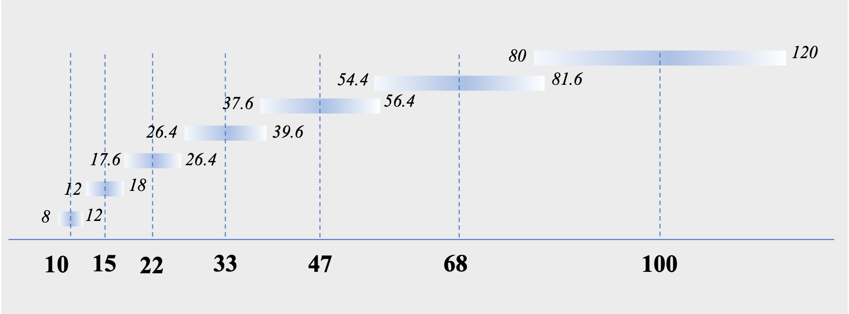
E6 series (tolerance ±20%) of 10 to 100μF capacitance
How To Use Al-Ecap Safely
Temperature has the greatest effect on Al-Ecap lifetime
Failure of Al-Ecap is caused by environmental factors such as temperature, atmospheric pressure, and vibration, as well as electrical factors such as operating voltage, ripple current, and charge/discharge duty cycle. Of these factors, temperature has the greatest impact on Al-Ecap life. As temperature rises, chemical reactions inside the Al-Ecap accelerate, shortening its life. In addition to ambient temperature, Al-Ecap's self-heating due to ripple current (Section 3.2 (3)) and radiation heat from other heat-generating components also affect Al-Ecap lifetime. Table 4 shows the factors that cause temperature rise, precautions, and actions.

Al-Ecap used for output smoothing in switching power supplies generates self-heating due to the large load current from the input side and voltage fluctuations caused by high switching frequency from the load side. This heat causes evaporation of the electrolyte, which can lead to Al-Ecap failure*04. For this reason, it is essential to use Al-Ecap at or below the upper category temperature.
*04 This capacitor is used to remove high-frequency AC components after smoothed voltage on the primary side of the power supply is boosted and stepped down by high-wave switching. Capacitors with high capacitance and low ESR are used in this application.
In addition to high temperatures, attention must also be paid to low temperatures, as the electrolyte in Al-Ecap becomes more viscous at low temperatures and its ionic conductivity is greatly reduced, resulting in a decrease in capacitance of several tens of percent and an increase in ESR*05.
*05 AIC tech web site, https://www.aictech-inc.com/information/capacitor_troubleshooting01.html
Al-Ecap has polarity and rated voltage
Al-Ecap is a polarized capacitor and has a set rated voltage.
Reverse voltage
When a reverse voltage is applied to the Al-Ecap, the dielectric insulation rapidly decreases and current continues to flow through the Al-Ecap. As a result, the Al-Ecap generates heat, which can causes serious problems such as short circuits, electrolyte leakage, smoking, ignition, and capacitor case rupture. Reverse connections, formation of circuit loops, and insufficient bias voltage with superimposed ripple current can lead to the application of reverse voltage to the Al-Ecap (Fig.3).
Overvoltage
Overvoltage breaks down the dielectric. This causes a current to flow into the Al-Ecap, heating it and raising its internal temperature above the boiling point of the electrolyte. If the pressure of the electrolyte vapor makes the pressure valve open, the electrolyte leaks out and leads to failure *06 .
*06 Imam A. M., et al. “Electrolytic Capacitor Failure Mechanism Due to Inrush Current.” IEEE Industry Applications Annual Meeting: pp.730-736. Sept. 2007.[27]
Voltage Fluctuation
Excessive ripple voltage, voltage fluctuations in the commercial power supply, or pulse voltage can cause overvoltage or reverse voltage to be applied to the capacitor (Fig.3). To avoid such risks, the following points should be checked in advance.
- Are there any voltage fluctuations?
- Whether the voltage’s peak value (Vtop) exceeds the rated voltage
- Whether the negative peak value (VVbottom) of the fluctuating voltage exceeds zero, resulting in a reverse voltage
- Is the range of fluctuation of the peak value(Peak to Peak : P to P ) appropriate, and is excessive charging and discharging cycle repeated?
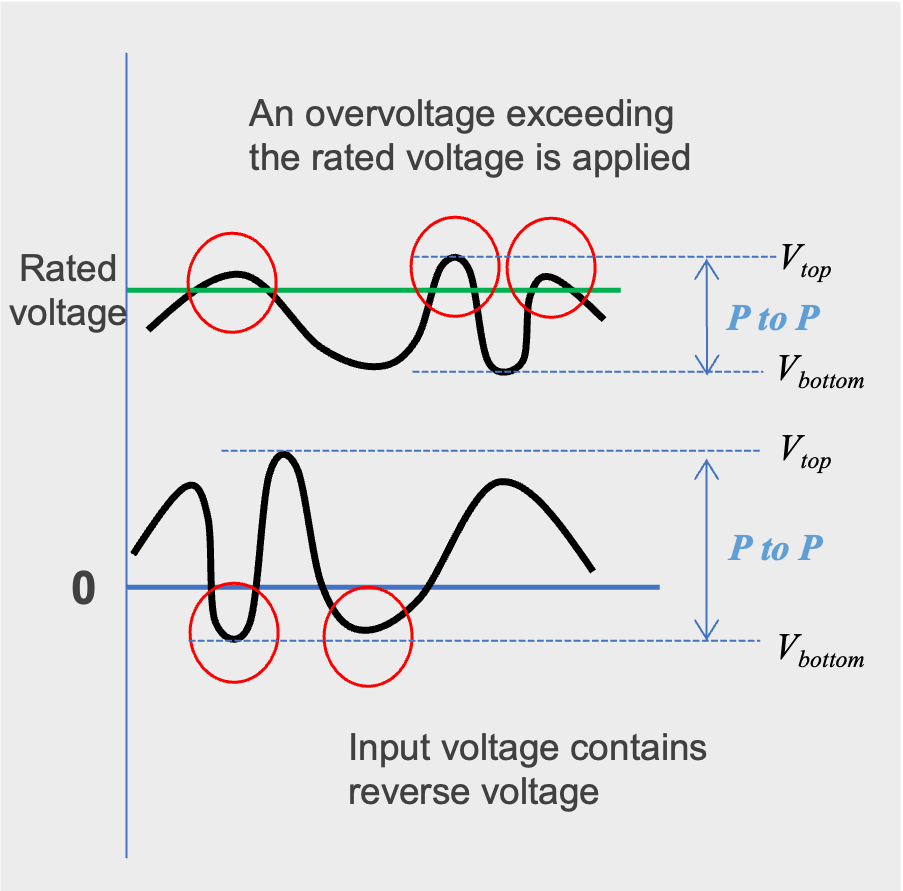
Voltage fluctuation
Capacitors in series, Voltage divider
In a series connection of Al-Ecap, individual capacitors are subjected to different magnitudes of voltage (Vn); the magnitude of Vn depends on the magnitude of the leakage current of the individual Al-Ecap. An Al-Ecap with high leakage current in series may be subjected to a voltage higher than its rated voltage, resulting in a short-circuit failure. For this reason, when connecting Al-Ecap in series, each capacitor should be connected in parallel with a resistor (voltage divider resistor) to balance the voltage (Fig.4).
To ensure uniform voltage distribution across the individual Al-Ecaps connected in series, use Al-Ecaps with higher voltage ratings and higher derating ratios to reduce the leakage current range across the individual Al-Ecaps, thereby increasing reliability. Furthermore, by using Al-Ecaps from the same production lot, the leakage current behavior can be made uniform with respect to temperature and voltage variations*07.
*07 AIC tech web site, https://www.aictech-inc.com/information/capacitor_troubleshooting01.html
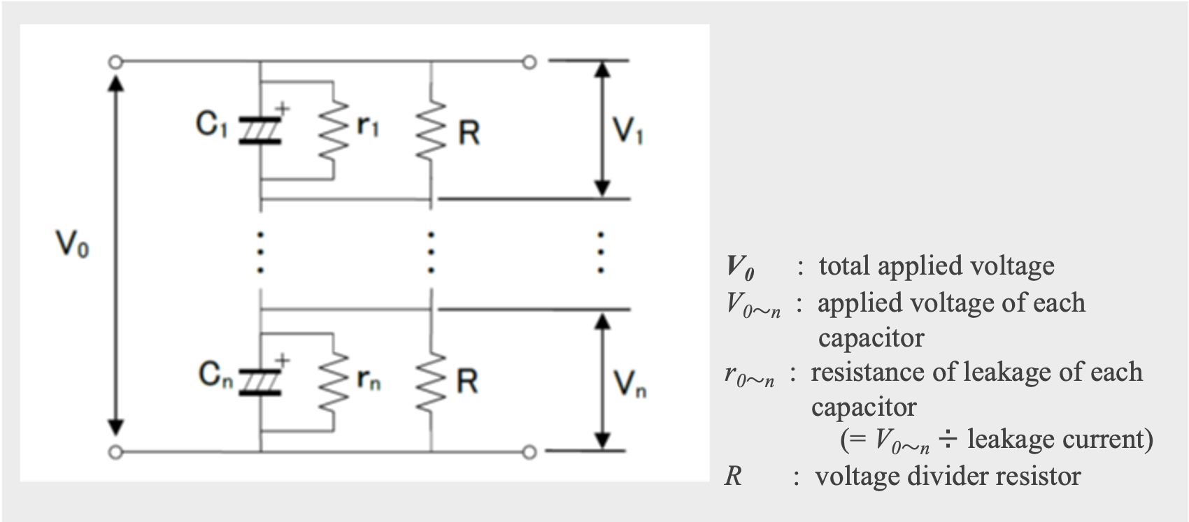
Capacitor in parallel with a resistor (voltage divider resistor) to balance the voltage
How To Use Al-Ecap Safely
Self-healing (SH) and voltage
Self-healing (SH), described in section 2.4 (1), is the property that most affects MF-cap reliability*08. Mild SH isolates the initial failure point that occurs at a localized defect (weak point) in the MF-cap. As the number of isolated defects increases, the capacitance of the MF-cap gradually decreases and it fails safely. However, as explained in section 2.3 (3), depending on the size and number of defects, SH may not operate effectively, and carbon deposition due to carbonization of the film and damage to the overlapping dielectric film may lead to destructive failure. Also, MF-cap can tolerate twice its rated voltage for a limited time. However, if an anomaly such as dielectric breakdown or excessive current pulses (high dU/dt) occur in the MF-cap, the contacts of the deposition and current-collecting electrodes can be damaged, resulting in reduced capacity and open failures.
*08 Lin, F., et al., “On the failure mechanism of metallized polypropylene pulse capacitors.” Conference on Electrical Insulation and Dielectric Phenomena, Annual Report Vol. 2 (2000): pp. 592-595. [15]
Borghetti, A., et al., “Tests on self-healing metallized polypropylene capacitors for power applications.” IEEE Transactions on Power Delivery Vol. 10 No. 1 (1995): pp. 556-561. [16]
MF-cap self-heating generated by ripple current
In the case of MF-cap as DC link capacitor, ripple current is a major failure factor; the ability of an MF-cap to withstand continuous ripple currents depends on the frequency of the ripple current and the capacitor's own heat dissipation power. If the power generated by the capacitor itself is greater than the power that can be dissipated by its surface, self-heating can be significant. The self-heating temperature of a capacitor depends on its equivalent series resistance (ESR), ripple current, and thermal resistance between the case and ambient temperature. Self-heating raises the temperature of the capacitor, leading to a decrease in withstand voltage and, in the worst case, may result in the melting of the capacitor element*09. For this reason, it is important that the ambient temperature Ta and the core temperature Tc of the capacitor due to self-heating be kept below 70°C (Eq. 01).
*09 Gallay, R. “Metallized Film Capacitor Lifetime Evaluation and Failure Mode Analysis.” Proceedings of the CAS-CERN Accelerator School: Power Converters: pp. 45-56. May 2014.[1]

Also, it is necessary to pay sufficient attention to radiation from heat-generating components (transformers, MOSFETs, resistors, etc.) adjacent to the MF-cap, mounting the MF-cap in a location where heat can accumulate inside the equipment or on the board where convection current is likely to stagnate, and heat transfer from bus bars, etc. connected to the MF-cap (Fig, 5).
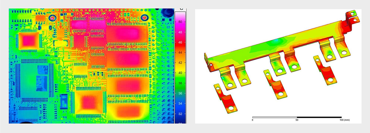
Temperature distribution of circuit board and bus-bar
Oxidative degradation of the metalized electrode
Large ripple currents and high voltages result in electrochemical corrosion of the deposition electrode, gradually oxidizing the aluminum to aluminum oxide. Oxidative degradation of metalized electrodes is one of the major causes of MF-cap failure. Factors that contribute to oxidative degradation include voltage, temperature, electrode thickness, stress, and ripple frequency*10. Cavallini et al. studied the effects of AC voltage and temperature on MF-cap degradation and reported that peak voltage has the greatest effect on capacitor aging*11 . In general PP type MF-caps tend to be less sensitive to ripple current than those with PET.
The thickness of metalized electrode is typically less than 100 nm, and the oxidation of metalized electrode progresses rapidly when voltage is applied in the presence of moisture. For this reason, strictly moisture control is used in the MF-cap manufacturing process to eliminate moisture from the MF-cap. Therefore, the use of MF-cap in areas subject to water, salt water, oil, etc., or condensation conditions must be avoided as much as possible*12.
*10 Reed, C.W. et.al., “The Fundamentals of Aging in HV Polymer-film Capacitors.” IEEE Transactions on Dielectrics and Electrical Insulation Vol. 1 No. 5 (1994): pp. 904-922.[2]
Makdessi, M., et al., “Accelerated Ageing of Metallized Film Capacitors under High Ripple Currents Combined with a DC Voltage.” IEEE Transactions on Power Electronics Vol. 30 No. 5 (2015): pp. 2435-2444.[12]
El-Husseini, et al., “Manufacturing technology effect on current pulse handling performance of metallized polypropylene film capacitors.” Journal of Physics D: Applied Physics Vol. 36 No. 18 (2003): pp. 2295-2303[13]
*11 Cavallini, et.al., “Models for Degradation of Self-healing Capacitors Operating under Voltage Distortion and Temperature.” Proceedings of the 6th International Conference on Properties and Applications of Dielectric Materials: pp. 108-111. June 2000.[14]
*12 When using capacitors with resin coating or resin embedding to improve moisture resistance, please contact the manufacturer.
Chemical components in the resin may permeate into the capacitor and cause deterioration of its characteristics.
If the entire product is coated with resin, it may be affected by thermo-mechanical stress due to thermal expansion and contraction.
Conclusions
We conduct reliability verification and quality control activities from development to delivery from the three perspectives of “design reliability verification and quality control,” “manufacturing quality control,” and “product quality assurance and quality control. We are working to achieve the quality expected by our customers and the quality that satisfies them. Our Al-Ecap has an estimated actual failure rate of approximately 0.3 FIT, an extremely low failure rate that is approximately 1/10 of that of typical semiconductor devices.
However, capacitors could fail due to various factors such as design defects, material wear, operating temperature, voltage, current, humidity, and mechanical stress. Failures can be divided into catastrophic failures due to overstress and wear failures due to degradation. Table 5-01 summarizes the major failure modes, failure mechanisms, and stress factors for Al-Ecap, MF-cap, and MLCC.
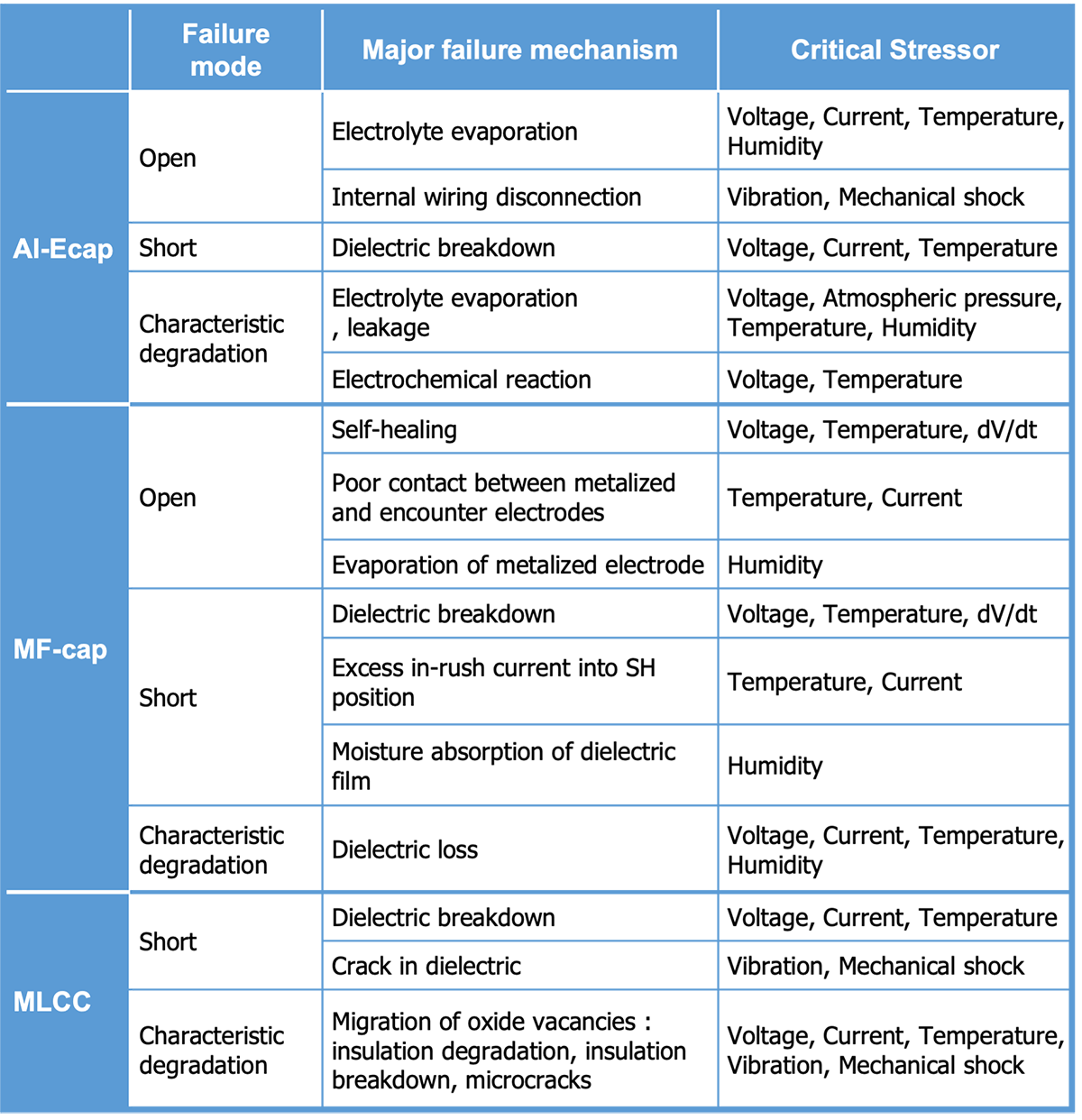
Customers are requested to properly select capacitors with quality and reliability that meet the requirements of their equipment. When using capacitors, please do not apply stress beyond the capacitor specifications, apply appropriate safety design and safety measures to the equipment, and thoroughly evaluate the reliability and safety before use. Please refer to our product catalogs and specifications for individual capacitor specifications and specific precautions. If you have any questions, please contact us.

Editorial supervision/Kazuyuki Iida
General Advisor, AIC tech Inc.
Born in the Tokyo area in 1956
M.S. of Sc, Sophia University, Tokyo, Japan. 1982
Over 35 years experience with knowledge on capacitor technology, i.e. R&D for high-performance capacitor and its materials, marketing activities at Hitachi Chemical Co, Ltd. and Hitachi AIC Inc. and Contributed articles on capacitors to public relations magazines, trade journals, and various handbooks.
Instructor of capacitor technology at the Technical Training Institute of Hitachi, Ltd. from 2005 to 2015.
General advisor to AIC tech Inc. from 2020.
- "Tantalum Electrolytic Capacitor"
The Electrochemical Society of Japan (ed.) Maruzen Handbook of Electrochemistry, 5th Edition, Chapter 15, Capacitors, Section 15.2.4 b (1998) - "Development Trend and Material Technology of Tantalum-Niobium Capacitors"
Technical Information Association of Japan Seminar June 2008 - Lead-Free Surface Mount Film Capacitors MMX-EC, MML-EC Series
Hitachi Chemical Technical ReportNo. 48. Product Introduction 2007 - "Film Capacitors for Electronic Devices"
Maruzen Capacitor Handbook, 5th Edition, Chapter 5, Film Capacitors, Section 5.2 (2009). - "Film capacitor MLC series for new energy"
Shinkobe Electric Co., Ltd. Shinkobe Technical Report Np. 22 (2012).
PDF Download
