Aluminum Electrolytic Capacitors
Resources (PDF)
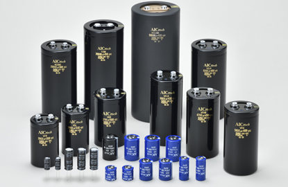
Aluminum Electrolytic Capacitors
Screw Terminal Type Aluminum Electrolytic Capacitor
| Type / Series | Feature | Useful Life time [h] | Operating Temperature range [℃] | Standard product | Small-sized product | High-reliability product | Operating voltage[V.DC] | Capacitance range[µF] | |
|---|---|---|---|---|---|---|---|---|---|
| Standard | VF UPGRADE! | Standard | 4,000 | -40〜+85 | ◯ | 6.3〜600 | 560〜680,000 | ||
| VG UPGRADE! | 105℃, Standard | 4,000 | -40〜+105 | ◯ | 25〜500 | 680〜330,000 | |||
| VFL UPGRADE! | Long-life, Standard | 8,000 | -40〜+85 | ◯ | 350〜550 | 680〜27,000 | |||
| VGL UPGRADE! | 105℃, Long-life, Standard | 8,000 | -40〜+105 | ◯ | 350〜500 | 680〜27,000 | |||
| VFH UPGRADE! | Long-life | 20,000 | -40〜+85 | ◯ | ◯ | 350〜500 | 680〜27,000 | ||
| High-ripple current | VFR UPGRADE! | Small-sized, High-ripple current | 4,000 | -40〜+85 | ◯ | ◯ | 350〜500 | 820〜27,000 | |
| VGR UPGRADE! | Small-sized, High-ripple current | 4,000 | -40〜+105 | ◯ | ◯ | 350〜500 | 680〜22,000 | ||
| VFLR UPGRADE! | Small-sized, High-ripple current | 8,000 | -40〜+85 | ◯ | ◯ | 350〜500 | 820〜27,000 | ||
| VGLR UPGRADE! | Small-sized, High-ripple current | 8,000 | -40〜+105 | ◯ | ◯ | 350〜500 | 680〜22,000 | ||
| VFHR UPGRADE! | High-ripple current, Long-life | 20,000 | -40〜+85 | ◯ | ◯ | 350〜500 | 680〜22,000 | ||
| Large-capacitance | HCGWA | Ultra small | 4,000 | -10〜+85 | ◯ | ◯ | 350〜500 | 5,600〜57,000 | |
| HCGW2 UPGRADE! | Ultra small | 4,000 | -10〜+85 | ◎ | 400〜500 | 7,500〜33,000 | |||
| HCGW3 UPGRADE! | Ultra small | 4,000 | -10〜+70 | ◎ | 350〜500 | 10,000〜51,000 | |||
| FXW UPGRADE! | Ultra small, Long-life | 8,000 | -10〜+85 | ◯ | ◯ | 350〜450 | 9,000〜45,000 | ||
| FXW2 UPGRADE! | Ultra small, Long-life | 8,000 | -10〜+85 | ◎ | ◯ | 350〜500 | 7,900〜42,000 | ||
| Not recommended for the new design. | HCG7A | ★Recommended series :VF" | 4,000 | -25〜+85 | 6.3〜100 | 3,300〜680,000 | |||
| HCGF5A | ★Recommended series :VF" | 4,000 | -25〜+85 | 160〜450 | 270〜39,000 | ||||
| HCGF6A | ★Recommended series :VF" | 4,000 | -25〜+85 | 400〜500 | 1,200〜22,000 | ||||
| FXA | ★Recommended series :VFL" | 8,000 | -40〜+85 | 350〜450 | 1,000〜18,000 | ||||
| FX2 | ★Recommended series :VFL" | 8,000 | -40(-25)〜+85 | 400〜600 | 1,000〜22,000 | ||||
| FX3 | ★Recommended series :VFL" | 8,000 | -40〜+85 | 400〜500 | 1,200〜22,000 | ||||
| FXR3 | ★Recommended series :VFLR" | 8,000 | -40〜+85 | 400〜500 | 1,800〜22,000 | ||||
| HXA | ★Recommended series :VFH" | 20,000 | -40〜+85 | 350〜450 | 1,000〜15,000 | ||||
| HCGHA | ★Recommended series :VG" | 4,000 | -40〜+105 | 25〜400 | 330〜330,000 | ||||
| GXA | ★Recommended series :VGL" | 8,000 | -40〜+105 | 350〜450 | 1,000〜15,000 | ||||
| GX2 | ★Recommended series :VGL" | 8,000 | -40〜+105 | 400〜500 | 1,000〜10,000 | ||||
| GX3 | ★Recommended series :VGL" | 8,000 | -40〜+105 | 400, 450 | 1,500〜12,000 | ||||
| GXR3 | ★Recommended series :VGLR" | 8,000 | -40〜+105 | 400, 450 | 2,200〜18,000 | ||||
Snap Mount Type Aluminum Electrolytic Capacitor
| Type / Series | Feature | Useful Life time [h] | Operating Temperature range [℃] | Standard product | Small-sized product | High-reliability product | Operating voltage[V.DC] | Capacitance range[µF] | |
|---|---|---|---|---|---|---|---|---|---|
| Standard | HP3 | Standard | 4,000 | -40〜+85 | ◯ | 16〜450 | 120〜33,000 | ||
| HU3 | 105℃, Standard | 4,000 | -40〜+105 | ◯ | 16〜450 | 68〜33,000 | |||
| HU UPGRADE! | 105℃, Small-sized | 4,000 | -40(-25)〜+105 | ◎ | 200〜550 | 82〜2,200 | |||
| ZL UPGRADE! | 105℃, Small-sized | 5,000 | -40(-25)〜+105 | ◯ | 200〜550 | 82〜2,700 | |||
| Long -life | HL UPGRADE! | 105℃, Small-sized | 8,000 | -40(-25)〜+105 | ◯ | ◯ | 200〜500 | 56〜2,700 | |
| YL | 105℃, Small-sized | 10,000 | -25〜+105 | ◯ | ◯ | 400〜500 | 82〜680 | ||
| XL1 | 105℃ | 15,000 | -40〜+105 | ◯ | ◯ | 200〜450 | 56〜1,800 | ||
| Special application | UW | Ultra small | 2,000 | -10〜+105 | ◎ | 450 | 210〜1,150 | ||
| CU | 105℃, side-vent type, High-ripple current | 4,000 | -25〜+105 | ◯ | 400〜500 | 120〜1,200 | |||
| ZR2 NEW! | High-ripple current | 5,000 | -25〜+105 | ◯ | 400, 450 | 180〜1,500 | |||
| ZR | High-ripple current | 5,000 | -40〜+105 | ◯ | ◯ | 400, 450 | 150〜680 | ||
| PS2 NEW! | High-ripple current, large capacitance | 4,000 | -40(-25)〜+85 | ◯ | 200〜600 | 180〜4,700 | |||
| US2 NEW! | High-ripple current, large capacitance | 4,000 | -40〜+105 | ◯ | 200〜450 | 330〜4,700 | |||
| DH | Charge-Discharge | 5,000 | -25〜+105 | ◎ | 400, 450 | 82〜680 | |||
| HW UPGRADE! | Flash | ー | -20〜+55 | ◎ | 330〜450 | 320〜3,800 | |||
| HS UPGRADE! | Flash | ー | -20〜+55 | ◯ | 330〜450 | 300〜3,100 | |||
Radial Type Aluminum Electrolytic Capacitor
| Type / Series | Feature | Useful Life time [h] | Operating Temperature range [℃] | Standard product | Small-sized product | High-reliability product | Operating voltage[V.DC] | Capacitance range[µF] | |
|---|---|---|---|---|---|---|---|---|---|
| Standard | HU | Standard | 2,000 | -25〜+105 | ◯ | 200〜450 | 8.2〜560 | ||
| HL | Standard, Long-life | 5,000 | -25〜+105 | ◯ | 200〜450 | 8.2〜560 | |||
FAQs
What quality standards do these capacitors meet?
Our aluminum electrolytic capacitors, including series such as VF, VG, VFL, and VGL, meet rigorous quality standards to ensure exceptional reliability and performance. We ensure compliance with the RoHS directive, which restricts the use of hazardous substances in electrical and electronic equipment. Our capacitors meet are the highest industry standards.
Can these capacitors be customized for specific applications?
Yes, we offer customization options for our aluminum electrolytic capacitors across various series, including VF, VG, VFH, and others. For example, we can add a Charge-Discharge function to our regular series, such as VF, VG, VFL, VGL, VFH, FXA, FX2, HXA, GXA, and GX2. This allows us to tailor the capacitors to meet specific electrical characteristics and operational requirements based on your unique needs.
How do AIC Tech's capacitors handle high ripple currents and what makes them suitable for such applications?
Our aluminum electrolytic capacitors, particularly the high-ripple current series like VFR, VGR, VFLR, VGLR, VFHR, and others, are engineered to handle high ripple currents with outstanding efficiency. We utilize advanced design techniques that enhance these capacitors' ability to withstand high ripple currents without overheating or degrading. The VFHR and VFR series, for instance, offer long-life and high-ripple current capabilities, making them ideal for even the most demanding applications.
How do AIC Tech's capacitors perform in harsh environmental conditions, such as high humidity or corrosive atmospheres?
We design our aluminum electrolytic capacitors, such as those in the VGL and VFH series, to perform reliably under specified environmental conditions. Our capacitors are engineered to operate within wide temperature ranges, from -40°C to +105°C, depending on the series. However, we recommend avoiding exposure to corrosive atmospheres or excessive humidity, as these conditions can lead to capacitor failures. Proper environmental controls are essential to ensure reliable performance in such environments.
Can these capacitors be used in applications involving high-frequency currents or harmonics?
Yes, our aluminum electrolytic capacitors can be effectively used in applications involving high-frequency currents or harmonics. We offer series such as VFR and VGR, which are specifically designed to handle frequency and harmonic conditions. It’s important to select the appropriate series based on the frequency characteristics of your application to ensure optimal performance.
What is the typical lifespan of these capacitors, and how does operating temperature affect their longevity?
The typical lifespan of our aluminum electrolytic capacitors varies by series. For example, our VFH and VFHR series offer a lifespan of up to 20,000 hours, while our VG and VF series offer around 4,000 hours. Operating temperature plays a crucial role in capacitor longevity; our capacitors should be used within their specified temperature ranges (-40°C to +105°C, depending on the series) to avoid thermal overload, which can reduce their lifespan. Proper cooling and maintaining temperatures within recommended limits are key to maximizing the lifespan of our capacitors.
Are these capacitors compliant with environmental and safety standards, such as the RoHS directive?
Yes, all of our aluminum electrolytic capacitors, including series like VF, VG, VFH, and others, comply with the RoHS directive. This ensures that our capacitors do not contain hazardous substances, meeting stringent environmental and safety standards and making them safe for a wide range of applications.
Basics of Aluminum Electrolytic Capacitors
What are Aluminum Electrolytic Capacitors?
Aluminum electrolytic capacitors are a specific type of capacitor that use an aluminum oxide layer as the dielectric. They are widely employed in electronics due to their relatively large capacitance-to-volume ratio and cost-effectiveness.

In an aluminum electrolytic capacitor, a thin oxide layer forms the dielectric on the etched anode foil (shown in blue), while the cathode foil (in yellow) and the electrolyte-soaked separator material are positioned on the other side; when rolled into a cylindrical “wound body,” these layers create a high-capacitance component. The etched anode foil increases surface area for higher capacitance, and the oxide film it supports is the primary insulating barrier. The separator (soaked with liquid or solid electrolyte) ensures continuous electrical contact between the foils, while maintaining separation to prevent direct short-circuit. Each foil is attached to inner lead tabs via cold weld spots, which eventually connect to the external terminals.
Internal structure of aluminum electrolytic capacitors
")
In a screw-terminal aluminum electrolytic capacitor, the aluminum terminal (1) at the top provides the main electrical connection, while the aluminum case (2) encloses and protects the internals. A plastic exterior material (3)—often PVC, PET, or a polyolefin film—wraps around the case for insulation and labeling. Directly under the terminal, a phenolic insulation cap (4) and an EPT rubber ring (5) help seal the capacitor from moisture and contaminants, and guide the terminal through the top. A silicone rubber vent (6) is built in to safely release gas if internal pressure rises.
Internally, aluminum leads (7) connect the external terminals to the wound “element,” which is stabilized by a petroleum pitch compound (8) at the base. This element (9) is the heart of the capacitor, made up of the rolled anode foil, cathode foil, and electrolyte-impregnated separators, all of which provide the large capacitance value characteristic of electrolytic capacitors.
In this diagram, the anode foil (around 100 µm thick) is coated with an aluminum oxide layer, which serves as the capacitor’s dielectric. A layer of electrolytic paper (typically 30 – 120 µm) is then soaked in an electrolyte solution (often ethylene glycol-based) and placed between the anode foil and the thinner cathode foil (20 – 50 µm). These layers are wound together to form the capacitor “element,” and the leads are attached to each foil for external connections.
The anodized aluminum foil’s oxide layer is the key to providing high capacitance, while the electrolyte-rich paper and cathode foil complete the circuit path and allow charge to be stored in the device.

Comparing aluminum electrolytic capacitors with other capacitor types
Compared to Film Capacitors
In power electronics, metalized film capacitors (often polypropylene-based) generally excel at high-voltage operation, low equivalent series resistance (ESR), and non-polar usage. They also maintain stable performance over wide temperature and frequency ranges, making them a preferred choice for AC output filters, snubbers, and other high-stress or high-ripple applications.
Aluminum electrolytic capacitors, by contrast, provide much higher energy density in a given volume and are more cost-effective for large capacitance values, but they have higher ESR and are limited to lower operating voltages (often below 700 V). Their performance also degrades more quickly over time, especially under thermal or electrical stress.

Compared to Ceramic Capacitors
Standard ceramic capacitors (like C0G/NP0 “Class I” dielectrics) are valued for their extremely stable capacitance over temperature and voltage, as well as very low losses. However, these devices typically offer much lower capacitance, making them less suitable for the bulk energy storage or DC-link buffering commonly required in power electronics.
While aluminum electrolytic capacitors have larger capacitance and are better at storing significant amounts of energy, they exhibit more variance with temperature and frequency, making them less precise for timing or resonant circuits.

Compared to Compared to Electric Double-Layer Capacitors (EDLCs)
Electric double-layer capacitors, or supercapacitors, store energy through the accumulation of charge in the interface (double layer) formed between activated carbon electrodes and an electrolyte. This mechanism enables very high capacitance values—often far exceeding what aluminum electrolytic capacitors can achieve.
By contrast, aluminum electrolytic capacitors, though offering less capacitance per device, can handle medium- to high-voltage requirements more readily and generally occupy a smaller volume for the same voltage rating.

Applications of aluminum electrolytic capacitors
Motor Drives
Aluminum electrolytic capacitors serve primarily as energy buffers and filters in motor drive inverters. They smooth out both low-frequency ripple (50 – 200 Hz) from the AC input and high-frequency switching ripple (8 – 20 kHz) from the inverter. Ensuring a low Equivalent Series Resistance (ESR) and managing self-heating through proper cooling or heat-sink mounting are critical for extending their service life, especially in higher-power or high-voltage systems where multiple capacitors may be placed in series.

VFH: A long-life aluminum electrolytic capacitor rated at 350–500 V, with capacitance from 680 µF up to 27,000 µF and a 20,000‑hour service life. Ideal for industrial power electronics and motor drives that require robust bulk capacitance and excellent ripple handling.
VGLR: A high-ripple current series spanning 350–500 V and offering 680–22,000 µF with a 5,000‑hour rating. Suited for converters, inverters, and power supplies demanding compact form factors and reliable performance under heavy ripple loads.
Renewable Energy System
In solar and wind power inverters, aluminum electrolytic capacitors are used in the DC link to stabilize voltage and filter out ripple currents. For higher system voltages (e.g., 600 – 1000 V), multiple electrolytics may be connected in series, but designers must include balancing or voltage-divider resistors. Although film capacitors are becoming more common in very large or high-voltage wind applications due to overvoltage tolerance and longevity, electrolytics remain a cost-effective solution where size and voltage requirements permit.

VG: A general-purpose aluminum electrolytic capacitor covering 25–500 V, with capacitances from 680 µF up to 330,000 µF and a rated life of 2,000 hours. Designed for wide-ranging power applications and moderate ripple loads.
VGR: Optimized for 350–500 V, featuring 680–22,000 µF and a 2,000‑hour service life. Suitable for power supplies and converters that demand robust bulk capacitance and moderate ripple performance.
VGLR: A high-ripple current series operating at 350–500 V, offering 680–22,000 µF with a 5,000‑hour rating. Ideal for applications requiring a balance of compact size, ripple endurance, and reliability.
Servo Drivers
Servo drivers use aluminum electrolytic capacitors in their DC link to provide a stable voltage source for the inverter stage that rapidly switches power to the servo motor. Because servo applications can feature frequent speed or torque changes, the capacitor must handle high ripple currents and momentary power surges. Snap-in types with high ripple ratings are common, while larger screw terminal capacitors may be deployed in industrial-scale servo systems.

ZL: Aluminum electrolytic capacitors rated 200–550 V, offering 82–2,700 µF and a 3,000‑hour lifespan. These serve as compact, general-purpose solutions for moderate-voltage filtering and smoothing applications.
VFLR: High-ripple-current capacitor spanning 350–500 V, with capacitance of 820–27,000 µF and a 5,000‑hour rating. Ideal for industrial inverters and motor drives where robust ripple handling is required.
VGLR: Operating at 350–500 V with 680–22,000 µF, rated for 5,000 hours. Well-suited to systems needing both reliable ripple performance and reduced form factor.
ZR2: Targeted toward 400–450 V lines, delivering 180–1,500 µF at a 3,000‑hour life. A good choice for applications that demand a moderate ripple rating in a smaller footprint.
FXW: Designed for 350–450 V, these capacitors feature large capacitance values (9,000–45,000 µF) and a 5,000‑hour service life, making them suitable for high-energy buffer circuits and power supplies.
FXW2: An extension of the FXW series covering 350–500 V with 7,900–42,000 µF and a 5,000‑hour rating. Provides a compact form factor for high-capacitance needs in demanding power electronics environments.
Switching Mode Power Supplies (SMPS)
In SMPS, aluminum electrolytic capacitors appear on both the PFC (Power Factor Correction) output and the main regulator output. They smooth the rectified voltage, buffer transient loads, and filter high-frequency ripple generated by switching transistors. Their relatively high energy density and cost-effectiveness make them well-suited for these duties, though it is essential to select low-ESR types and account for operating temperature to ensure a long service life.

ZL: Designed for 200–550 V with capacitance from 82–2,700 µF and a 3,000‑hour lifespan. A compact, general-purpose choice for moderate-voltage applications.
HL: Spanning 200–500 V, offering 56–2,700 µF and a 5,000‑hour rating. Suited for applications demanding enhanced service life under moderate voltage and current conditions.
HU: Rated 200–550 V with 82–2,200 µF and a 2,000‑hour life. Provides a cost-effective solution for general power supply filtering and smoothing tasks.
Pulsed Power Supply
Pulsed systems (e.g., X-ray generators, welding equipment) rely on capacitors for short, high-power bursts of energy. Aluminum electrolytics can discharge 30 – 40% of their voltage relatively quickly, making them suitable if frequent, full-voltage discharge is not required. Key selection factors include capacitance size (directly tied to stored energy), allowable ripple current, and low inductance (ESL) to minimize voltage spikes.

VFH: Rated 350–500 V with 680–27,000 µF and a 20,000‑hour lifespan. Suited for high-reliability industrial systems needing stable bulk capacitance.
VGLR: Operating at 350–500 V, delivering 680–22,000 µF over 5,000 hours. Ideal for power converters requiring higher ripple handling.
VF: Covers 6.3–600 V at 560–680,000 µF, rated for 2,000 hours. A versatile choice across low to medium-voltage filtering applications.
HCGW2: A 2,000‑hour capacitor for 400–500 V, offering 7,500–33,000 µF. Suited for mid-voltage power supplies or industrial filtering needs.
HCGW3: Built for 350–500 V with 10,000–51,000 µF and a 2,000‑hour rating. Provides large capacitance for demanding, higher-current circuits.
FXW: Designed at 350–450 V with 9,000–45,000 µF and a 5,000‑hour service life. Perfect for high-capacity DC links in moderate-voltage domains.
FXW2: Extends to 350–500 V at 7,900–42,000 µF, rated 5,000 hours. Offers a compact footprint for bulk energy storage in power electronics.
Uninterruptible Power Supply (UPS)
UPS systems use aluminum electrolytic capacitors in the DC link to help stabilize the inverter output and buffer short-term power interruptions, providing additional energy while batteries or generators come online. Over time, the electrolyte can dry out, so periodic replacement is usually necessary—especially in high-temperature or high-ripple environments. Screw terminal designs are common where large capacitance and high voltage ratings are required.

FXW: Rated 350–450 V with 9,000–45,000 µF and a 5,000‑hour lifespan. Provides large energy storage and is well-suited for high-capacitance DC-link designs.
FXW2: Covering 350–500 V, offering 7,900–42,000 µF at a 5,000‑hour rating. Ideal for moderate-voltage buffers in power electronics that need substantial capacitance.
HCGW3: Spanning 350–500 V, featuring 10,000–51,000 µF over a 2,000‑hour service life. Designed for high-capacity industrial filtering applications.
VF: A broad range from 6.3–600 V with 560–680,000 µF, rated at 2,000 hours. Covers everything from low-voltage supply filtering to mid-voltage energy reserves.
VG: Operating at 25–500 V and 680–330,000 µF, with a 2,000‑hour lifespan. Commonly used for general-purpose filtering and smoothing in power supplies.
HCGWA: Designed for 350–500 V, offering 5,600–57,000 µF at a 2,000‑hour rating. Provides high volumetric capacitance for demanding industrial or renewable power systems.
Traction Control System
In rail and automotive traction applications, aluminum electrolytic capacitors may supplement or be combined with film capacitors for auxiliary inverters or lower-voltage sections. They help manage the ripple current from power converters that drive large motors. Because traction systems often operate at high voltages and under harsh conditions, cooling provisions, mechanical robustness, and carefully rated ripple-current capabilities are crucial to capacitor longevity.

VF: Aluminum electrolytic series from 6.3–600 V with a broad 560–680,000 µF range and a 2,000‑hour rating. Serves as a versatile solution for low-to-mid voltage filtering.
VFL: Rated 350–550 V with 680–27,000 µF over 5,000 hours. A dependable choice for higher-voltage DC links and smoothing applications in industrial drives.
Manufacturing processes for aluminum electrolytic capacitors
① Etching (expanding surface area)
The processing for expanding the surface of aluminum foil.
High purity aluminum foil, 500mm wide and 0.1mm thick is continuously processed electrochemically by flowing direct current through a chlorine bath solution. The surface area is expanded 50-100 times for low-voltage use capacitors and 10-40 times for medium to high-voltage use capacitors.

② Forming (dielectric formation)
The process of forming the dielectric(Al2O3).
The dielectric is formed in a continuous electrochemical process by passing a voltage that is 120-200 percent of the working voltage through etched aluminum foil that is in a bath of boric acid ammonium. The dielectric is extremely thin, about 14Å/V.

③ Slitting
The formed aluminum foil(anode foil), cathode foil and electrolytic paper are slit according to the product size.
④ Winding
Electrolytic paper is inserted between the slit anode foil and the opposite cathode foil and rolled into a tube. Leads are connected because both electrode foils are concerted to a terminal. To prevent mechanical contact between the anode and cathode electrode foils, the electrolytic pass functions to hold the electrolytic liquid which is a cathode electrode.
⑤ Impregnation
The process of inserting the electrolytic liquid into the device by pressurization and depressurization. The electrolytic fluid is uses such things for solvents as boric acid and organic acid ammonium with ethylene glycol as the main medium. These have a very big effect on the life, frequency characteristics, range of operating temperature and temperature characteristics of the capacitor.
⑥ Assembly
After making holes on lead tab insulation cap are connected to lead.
⑦ Sealing
The impregnated device is sealed by an aluminum case and sealant to keep it airtight.
⑧ Reforming (aging)
This is the process of applying voltage at high temperature to debug, to form the dielectric that has been damaged during assembly and to shear the anode foil during slitting.
⑨ Inspection of all parts
Inspection is made of the external appearance and the electrical characteristics of all aged parts.
⑩ Sampling, packaging and shipping
An inspection is made according to fixed sampling standards and the capacitors that pass the inspection are packed and shipped. Detailed tests are made periodically to check quality.
Service Life of an Aluminum Electrolytic Capacitor
1. Factors affecting service life
Environmental factors affecting the service life of an aluminum electrolytic capacitor include temperature, humidity and vibration (environment), as well as electrical factors, applied voltage, ripple current and charging / discharging conditions. In capacitors for mid-to-high-voltage filters, temperature and applied voltage are the most important controlling factors. The estimated service life may be calculated based on the core temperature of the capacitor and the applied voltage.
1.1 Temperature Conditions
Impact on Service Life: Higher ambient temperatures accelerate the decrease in capacitance and increase the tangent change for the loss angle, primarily due to gas generation from the electrolytic solution.
Estimating Service Life: The service life can be extended by lowering the core temperature, which can be achieved by reducing ambient temperature, lowering load current, or improving capacitor design to enhance cooling.
1.2 Voltage Conditions
Impact on Service Life: Applying voltage below the rated level can extend the service life. However, if the voltage drops below 60% of the rated voltage, its impact on service life becomes negligible.
Voltage Management: It's crucial to keep the applied voltage below the rated level to prevent rapid deterioration, such as leakage current increase or internal pressure buildup, which can lead to safety vent activation or internal short circuits.
2. Other Factors Affecting Service Life
2.1 Reverse Voltage
Applying reverse voltage leads to the formation of an oxide film on the cathode foil, generating heat and gases, which significantly shortens service life.
2.2 Charge and Discharge
Frequent charging and discharging cause oxide film formation on the cathode foil, reducing the service life. General-purpose capacitors are not suitable for applications like photo flash or welding circuits.
2.3 Inrush Current
Inrush currents, which are significantly larger than normal currents, can occur when powering up devices like welding machines. While occasional inrush currents are manageable, frequent occurrences can drastically shorten the capacitor's service life.
Reducing Substances with Environmental Impact
As part of our initiatives for global environment protection under ISO 14001, we recommend products without any substances with environmental impact to our customers.
(1) Lead-free
Regarding Snap mount type and Radial type Aluminum Electrolytic Capacitors, our standard specification is to use Tin instead of Lead on the surface of terminal plating. We discontinued producing Tin + Lead plating. Regarding Screw terminal type Aluminum Electrolytic Capacitors, they do not contain Lead at all. Please contact us for details.
(2) Eliminating Chromate Treatment
The previous chromate treatment on the surface of bracket contained hexavalent chromium.
To avoid this material, we changed to trivalent chromium.
The surface treatment is changed but no change in size or other specification.
In addition to Lead-free, aluminum electrolytic capacitors that we produce have suited RoHS Directive.
(3) PVC-free
For PVC-free Snap mount type and Radial type Aluminum Electrolytic Capacitors, the capacitors are covered with PET insulating sleeve, and The bottoms not covered. Please contact us for other PVC-free products.
(4) Conform RoHS
All series (Screw terminal type Aluminum Electrolytic Capacitors, Snap mount type Aluminum Electrolytic Capacitors, Radial type Aluminum Electrolytic Capacitors) apply RoHS