Lifetime Estimation of Capacitors
(Electrolytic, Film Capacitors & More)
Contents
Lifetime Estimation of Capacitors
Basics of Lifetime Estimation
Bathtub curve
As mentioned in section 1.1 , the basic functions of capacitors are
- Block DC current
- Store or discharge an electric charge instantly
- Allow AC current to pass through it.
Capacitor failure is the loss or deterioration of these functions. Failure rate is defined the frequency with which an engineered system or component fails, expressed in failures per unit of time*01.
*01 JIS C 5003-1974 General Test Procedure of Failure Rate for Electronic Components
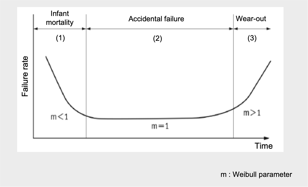
The failure rate is represented by the failure rate curve (bathtub curve) shown in Fig. 1. This curve is a graph of failure rate versus time that illustrates the failure rate tendencies of an item over its life span and used in reliability engineering and deterioration modeling. The 'bathtub' refers to the shape of a line that curves up at both ends, similar in shape to a bathtub. The bathtub curve has 3 regions :
(1) Infant mortality : The first region has a decreasing failure rate due to early failures.
(2) Accidental failure : The middle region is a constant failure rate due to random failures.
(3) Wear-out : The last region is an increasing failure rate due to wear-out failures, e.g. wear, fatigue, corrosion and oxidation of materials
The Bathtub Curve
Infant mortality and Wear-out
Infant mortality
The region (1) in Fig. 1 is called the infant mortality and failures during this period are referred to as initial failures. Initial failures are caused by potential design errors, process defects, or other weaknesses that were not foreseen by FMEA and become apparent in a short period of time due to temperature, voltage, or other stresses.
In the infant mortality phase, the curve typically begins with high failure rates that drop drastically as the component nears the end of its infancy. Therefore, failures that can be detected and removed during the manufacturing process. The process of removing initial failures is called debugging, which includes aging and screening. We conduct our own quality control methods and quality improvement activities, as well as our original inspections and screening technologies. We also promote reliability from the design and development stage, and conduct reliability design, design review, and verification through reliability tests to ensure reliability.
Wear out
The region (3) in Fig. 1 is called the wear-out phase and failures during this period are referred to as wear-out failures. Wear failures are due to wear and deterioration of the underlying structure and materials, and the failure rate begins to increase exponentially. In the case of aluminum electrolytic capacitors, the electrolyte evaporates (dry-up) due to environmental temperature or self-heating during use, resulting in failures such as decreased capacitance, increased tanδ and leakage current. During the wear-out phase, maintenance such as replacement is required.
Constant failure rate (Accidental failure rate)
The previous section indicates that initial failures are due to quality control and wear failures are due to inherent engineering or design issues. On the other hand, failures also occur during the period when the device, including equipment and capacitors, is in operation. In other words, it is a failure that is neither an initial failure nor a wear-out failure. This failure is called the constant failure rate (CFR) or the accidental failure rate. CFR phase is typically a flat graph representing CFR of a component during the “steady state” of the item’s operating life.
However, this phase only means that the failure rate is constant, not that the failure rate is zero. It means that there is a certain probability of failure, but that probability is constant. It is like throwing a dice and getting a one is accidental, but the probability is constant.*02
*02 The main causes of accidental failure include electrical overstress, such as overvoltage or excessive inrush current, as well as mechanical and physical stress. However, unless used under abnormal conditions beyond specifications, the expected life is sufficiently long and the product is designed so that actual use will not lead to wear failure.
Definition of failure rate
Failure rate includes the mean failure rate and the momentary failure rate.
Mean failure rate, FIT
The mean failure rate is the value obtained by dividing the total number of failures by the total operating hours, and units such as %/1,000h or ppm/1,000h are commonly used for capacitors. For components with low failure rates, it is expressed as the number of failures that occur during 109 hours of operation of an object. The unit is FIT (Failure In Time), where 1 FIT = 10-9/hour*03 (Eq. 01).

*03 Average number of failures per billion ( 109 ) hours. Often used for industrial products such as semiconductor components that are produced in large volumes and have extremely low failure rates.
For example, a mean failure rate of 300 FIT is 300×10-9 hours, or 3×10⁻⁷ hours. This means that for every 107 (10 million hours/piece) the product of the number of active samples and the operating time, 3 failures might be observed. It does not mean that the lifetime of one sample is 107 hours. Care must be taken when interpreting the mean failure rate.
The momentary failure rate and lifetime estimation
The momentary failure rate is the probability that a component or unit that was previously in operation will fail at time t. This value can also be understood as the number of products that fail per unit time in the time between time t and t + ΔT. In general, the term “failure rate” refers to the “momentary failure rate.
If the probability density of the momentary failure rate is exponential*04, the failure rate follows a χ2 distribution (chi-square distribution)*05 . There is a method to obtain the estimated number of failures N in the upper limit interval by conducting high-temperature load tests for several hundred to several thousand hours and analyzing the test results using the χ2 distribution*06, 07 .
*04 https://bellcurve.jp/statistics/course/8009.html
*05 Setoya et.al., “The Actual Condition of Reliability Prediction and Presumption of Semiconductor LSI”. ”The Journal of Reliability Engineering Association of Japan. Vol.40 No.6 2018
*06 ”Shinraisei dta kaiseki (Reliability data anlysis)”,JUSE Press. Ltd. (2009)
*05 JEDEC JESD-47
Specifically, the cumulative probability of failure Ft at time t tested under certain conditions can be expressed by the following equation using a confidence level R(%), a significance level α (1-R, %), and a degree of freedom β that depends on the number of failures r*08 (Eq. 02).
*08 JEITA EDR-4708B:Guideline for IC Reliability Qualification Plan

Since the expected lifetime can be considered the inverse of the time-dependent momentary failure rate Ft, the expected lifetime Lestimate can be obtained from Eq. 03, which is the inverse of Eq. 02.

For example, assuming that one capacitor fails during 1000 hours when 50 capacitors are tested under certain conditions (r = 1) , and estimating the lifetime with a confidence level of 95% (significance level α = 5%) *09, the lower limit Lshort and upper limit Llong of expected lifetime can be calculated as follows.
*09 A confidence level of 95% means that 95 times out of every 100 times a confidence interval is obtained from the sampled results, the population mean falls between the 95% confidence level and the population mean.


Since the lower limit of lifetime is important for the use of capacitors, the expected lifetime in this case is about 1 year.
Lifetime estimation and failure rate when no failures occurred in the test
It is difficult to detect accidental failures in products from which initial failures have been removed. This is because it is difficult to detect failures even when life tests are conducted under the specified condition. Therefore, if no failure is detected in the test, the upper limit of expected life cannot be determined. In this case, the lower limit of expected life Lshort is calculated as follows, assuming that α/2 in the denominator of Eq.04 is α.

Eq. 06 indicates that it is possible to estimate the life even if no failure is found in the test. However, in actual use, conditions such as temperature and voltage are often more relaxed than the test conditions, so the expected life obtained from the test can be corrected by the method described in Chapter 4.
As mentioned earlier, expected life and failure rate are inverses of each other. Therefore, the inverse of Eq. 06 is the upper limit of the failure rate, which is approximately 0.06%/1000 hours. The expected life of a capacitor can be considered as MTTF (Mean Time To Failure), which is the average time to failure, as long as the capacitor is not replaced due to degradation.
Factors of Capacitor Failure Rate
There are various factors in the lifetime and failure rate of capacitors. For example, Chapter 10 of MIL-HDBK-271F-Notice2 defines the failure rate λP of aluminum electrolytic capacitors as following Eq. 07. Among these factors, temperature and voltage have a significant effect on capacitor life. Therefore, proper derating condition of temperature and voltage make possible capacitor’s lifetime extend.

General Life Estimation Formula for Capacitors
The inverse of the failure rate is the life expectancy. Lifetime estimation formulas are used to predict the lifetime of capacitors. The formulas vary from manufacturer to manufacturer and take into account capacitor design and construction, reliability engineering theory and actual data. In general, capacitor stress factors are operating temperature, applied voltage, and ripple current, which are typical life factors. The general formula is expressed by Eq. 08, which includes the acceleration factor of each factor*10.
*10 A. Albertsen, ”Electrolytic capacitor lifetime estimation,“ Jianghai Europe GmbH, Tech. Rep., 2010. [40]
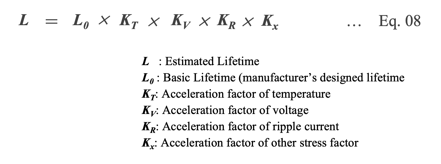
Each acceleration factor in Eq. 08 takes on a value specific to the capacitor type. The following sections discuss the life estimation equations for Al-Ecap, MF-cap, and MLCC.
Lifetime Estimation of Al-Ecap
The rated lifetime L0 of most Al-Ecaps ranges from 1,000 to 15,000 hours (0.11 to 1.71 years). However, the lifetime varies with temperature, applied voltage, and ripple current, and life estimates and acceleration factors vary from manufacturer to manufacturer. This is due to differences in electrolyte chemistry, capacitor topology, and testing methods among manufacturers. Moreover, each manufacturer's formulas for lifetime estimation and acceleration factor are not derived from basic theory, but are empirically derived in accordance with experimental data. For this reason, care must be taken in applying one manufacturer's acceleration rate to another.
This section outlines the basic relationship between Al-Ecap lifetime and temperature, voltage, and ripple current, as well as key points for estimating the lifetime.
Temperature acceleration factor KT and 10°C doubling rule
Capacitance and tanδ of Al-Ecap are parameters that vary greatly with temperature. At low temperatures, the capacitance decreases and tanδ increases as the conductivity of the electrolyte decreases. Also, when voltage is applied at high temperatures, the reaction between the electrode foil and the electrolyte generates a lot of gas. In other words, the chemical mechanism greatly affects the properties and life of Al-Ecap. For this reason, most manufacturers believe that the life of a capacitor follows Arrhenius' law and propose a temperature acceleration factor using the Arrhenius equation shown in Eq. 09.
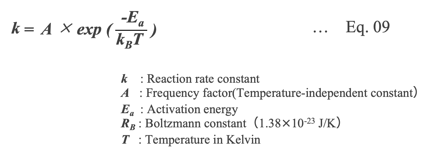
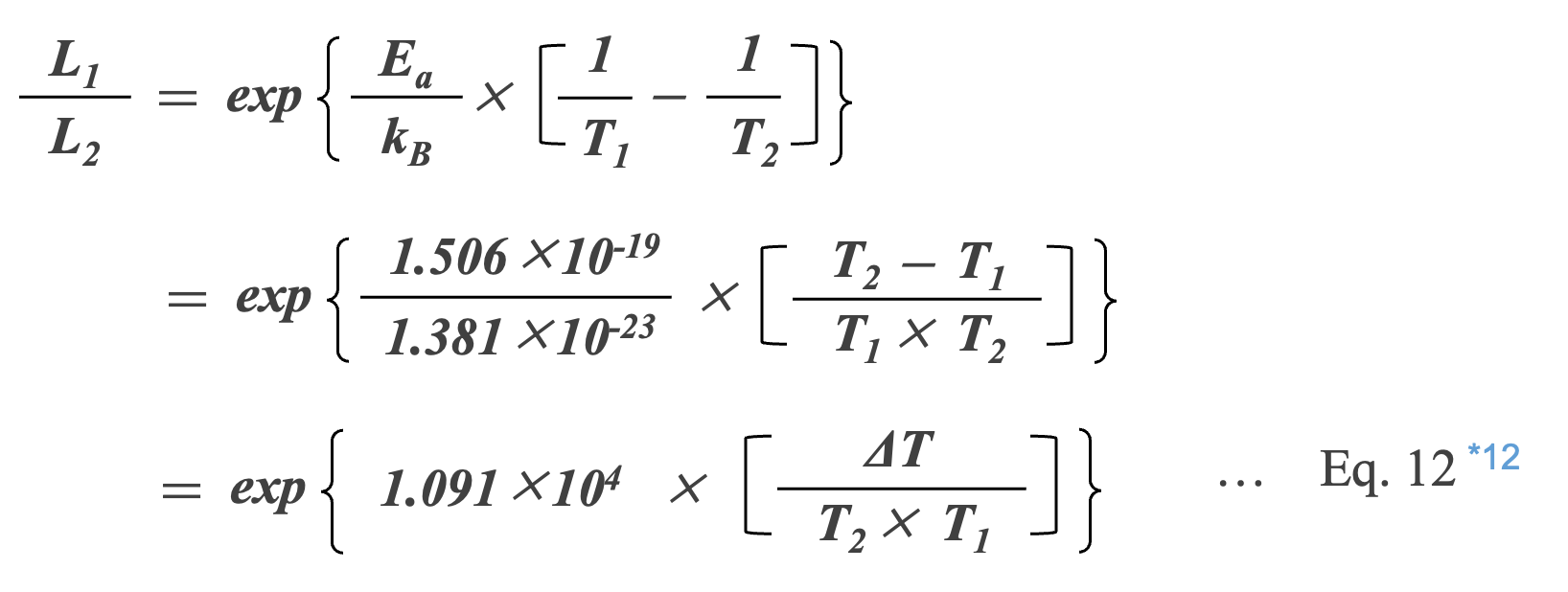
Taking the logarithm of Eq. 09 and considering that the reciprocal of the reaction rate is the lifetime L, the relationship between the lifetime and temperature can be expressed by Eq. 10.

The ratio of the lifetime L1 at temperature T1 to the lifetime L2 at T2, which is higher than T1, can be expressed by Eq. 11.
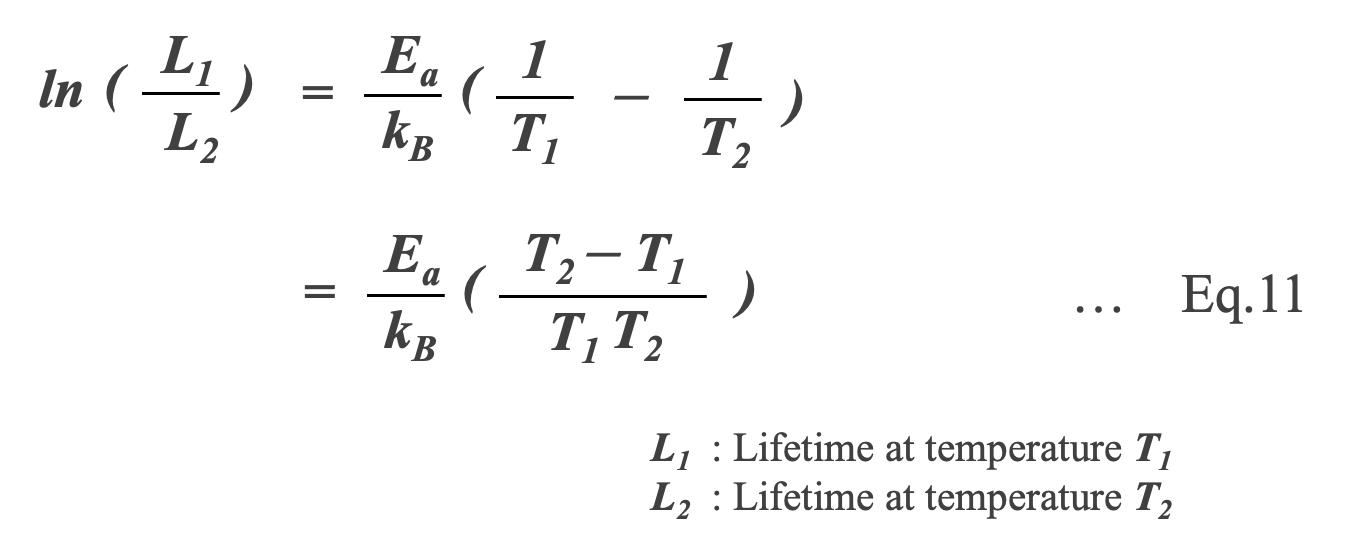
Assuming that the Al-Ecap failure is a reduction-oxidation reaction of aluminum oxide and that the activation energy Ea in Eq.11 is 1.506 × 10⁻¹⁹ J (0.94 eV) of the activation energy of aluminum oxide*11, Eq.11 can be rewritten as follows.
*11 H. Ma and L. Wang, “Fault diagnosis and failure prediction of aluminum electrolytic capacitors in power electronic converters," in 31st Annual Conference of IEEE Indus-trial Electronics Society, 2005 (IECON 2005), 2005, pp. 842{847.[42]
*12 ΔT=T2 – T1
Al-Ecap with a maximum operating temperature (upper category temperature) of 105°C. The ratio of the life time L95 when used at an ambient temperature of 95°C to the life time L105 at 105°C can be calculated as in Eq. 13 *13.
*13 P. Venet, et. al., ” Influence of aging on electrolytic capacitors function in static converters: Fault prediction method," European Physical Journal-Applied Physics, vol. 5, no. 1, pp. 71{83, 1999.[105]
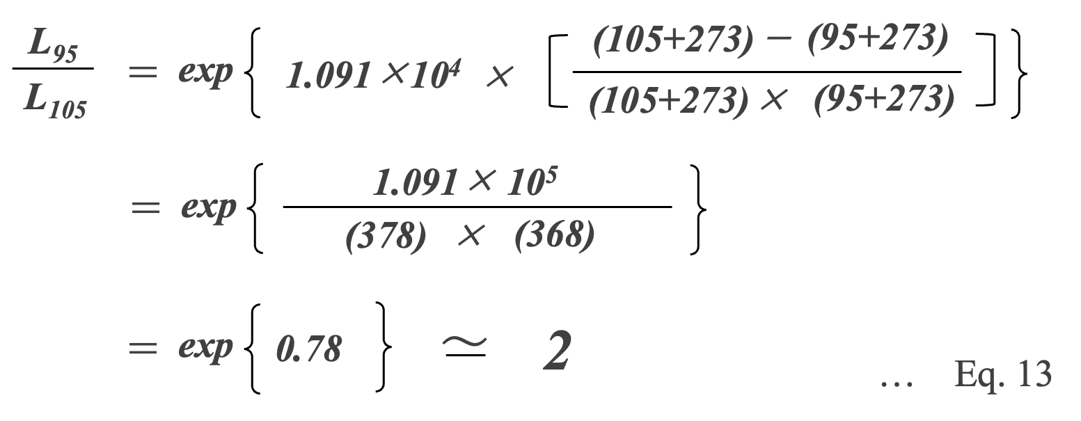
The calculation result of Eq. 13 shows that the lifetime L95 at a temperature of 95°C is estimated to be approximately twice that of L105 at 105°C. This means that 'for every 10°C decrease in operating temperature, the life of the capacitor is doubled. This is an empirical rule that shows the temperature acceleration of life, and is known as the so-called “10°C doubling rule”. Eq. 14, which is a generalization of Eq.12, is used as the temperature acceleration factor KT-EL*14.
*14 The lifetime of smaller capacitors is relatively dominated by the temperature acceleration factor KT, which depends on the electrolyte.

However, care must be taken when applying the “10°C doubling rule”. Eq. 13 assumes that the product of the upper category temperature and the operating temperature is “378 × 368” (= 1.391 × 10⁵), which may underestimate the lifetime by 10 to 40% at low temperatures*15. For example, the ratio between the lifetime L50 at 50°C and L60 at 60°C can be is calculated to be 2.76 (10°C 2.76 times law). This means that applying the “10°C doubling rule” at 50°C/60°C underestimates the lifetime by about 38%.
*15 S. Parler Jr, \Selecting and applying aluminum electrolytic capacitors for inverter applications," Cornell-Dublier, Tech. Rep., 2010. [106]

Voltage Acceleration Factor KV
Eq. 16 is widely used as an empirical model for voltage-acceleration factor, KV, which represents the effect of voltage on lifetime. This equation has been applied primarily to medium to large capacitors. When capacitors are used at high voltages, the dielectric is subjected to high voltage stresses, resulting in shortened capacitor’s lifetime. Applying a voltage that is sufficiently marginal to the rated voltage reduces the voltage stress on the dielectric and promotes healing of defective parts of the dielectric*16, which may significantly extend the capacitor’s lifetime. The multiplier n in Eq. 16 depends on the manufacturer, rated voltage, capacitance, and capacitor size, with values between 2 and 5 generally used*17.
*16 S. Parler Jr, “Deriving life multipliers for electrolytic capacitors," IEEE Power Electronics Society Newsletter, vol. 16, no. 1, pp. 11{12, 2004. [116]
*17 https://www.jstage.jst.go.jp/article/ieejjournal1888/95/5/95_5_384/_pdf/-char/ja
It is derived from an empirical law that shows the effect of voltage on insulators.

Ripple Current Acceleration Factor KR
Any ripple current present gradually increases the internal temperature of the capacitor so that the ambient operational temperature, capacitor surface temperature, and internal core temperature may all be significantly different*18, 19. For degradation failures of Al-Ecaps, it is generally assumed that the evaporation of solvent in the electrolyte is responsible for decreased performance parameters.
*18 M. L. Gasperi, \Life prediction model for aluminum electrolytic capacitors," in Conference Record of the 1996 IEEE Industry Applications Conference (IAS 1996), 1996, pp. 1347{1351. [88]
*19 G. Rhoads and A. Smith, “Expected life of capacitors with non-solid electrolyte," in IEEE 34th Electronic Component Conference, 1984, p. 156. [107]
The vapor pressure of ethylene glycol, a component in many electrolyte recipes, can change multiple orders of magnitude over standard capacitor operation temperatures. Depending on the temperature and the quality of capacitor construction, the solvent may readily evaporate at higher temperatures. This evaporation decreases electrolyte volume and increases the Al-Ecap’s ESR.
Therefore, in the lifetime estimation of a capacitor, it is necessary to consider not only the temperature acceleration factor KT but also the ripple acceleration factor KR , which takes into account the increase in internal temperature due to the ripple current.
Capacitor Generation of Heat Due to Ripple Current and Core Temperature
Capacitors have the role of smoothing voltage by removing ripple current. However, the ripple current generates Joule heat, which raises the temperature of the capacitor (self-heating, Fig. 2).
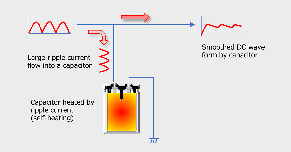
Diagram of ripple current removal by capacitor and heat generation by capacitor
The core temperature inside the capacitor due to ripple current can be calculated from the temperature rise, ΔT, due to a power (P) owing across an element with thermal resistance of Rth. The electrical power is dissipated across the capacitor due to resistive heating (P = I2×ESR) and the temperature rise can be calculated by Eq. 17.

*20 We may apply the following simplified formula to calculate temperature rise.

Al-Ecap’s ESR is not constant, but is a function of both internal capacitor temperature and frequency. Therefore, the center temperature of the capacitor (center temperature) Tc due to ripple current is expressed by Eq. 18, which considers the frequency and temperature dependencies of ESR and the ambient temperature Ta.

Factor KR
Temperature Measurement
Since the capacitor is not at a steady state temperature, there are three separate applicable temperatures, the ambient temperature, Ta, the capacitor surface temperature, Ts, and the capacitor core temperature, Tc. The ambient and surface temperatures are relatively easily measured. Unfortunately, while Tc is the most important temperature, it may difficult to obtain direct data while the capacitor is in operation. For large capacitors like a screw terminal type or a snap-in type, manufacturers might offer units with embedded thermocouples. These special samples may be run at full voltage and ripple for prototyping. However, this may not be feasible for smaller capacitors and many researchers and manufacturers either substitute the surface temperature or approximate the core temperature from surface temperature measurements.
ESR v.s. Temperature and Ripple Frequency
As already mentioned, Al-Ecap ESR is not constant, but is a function of both internal capacitor temperature and ripple frequency (Fig. 3).
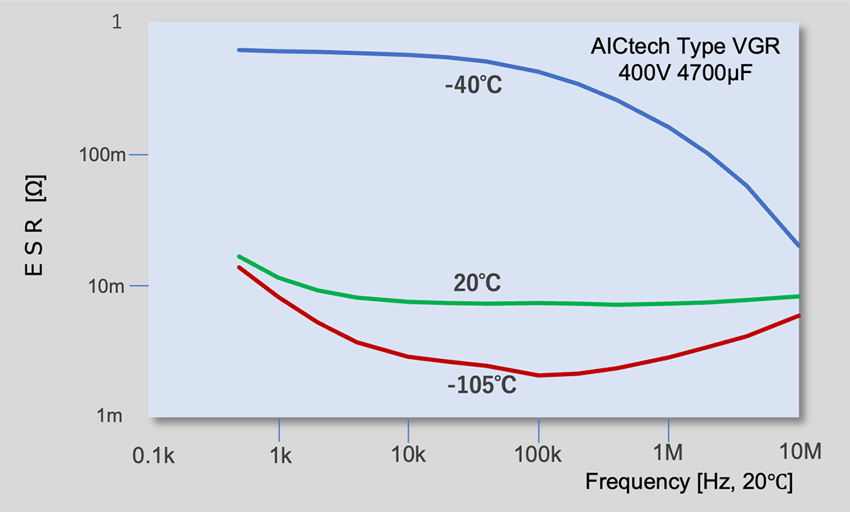
ESR v.s. Temperature and Frequency
Al-Ecap ESR is composed of three components, Rc, Rf , and RT (Eq. 19) *21. Rc is a constant resistance due to the foils, tabs, electrolyte, and other capacitor components. This resistance is a relatively small value (~10mΩ) which is constant with temperature and frequency. On the other hand, Rf and RT are the frequency and temperature dependent resistances. The frequency dependent resistance Rf is due to the alignment of dipoles in the dielectric oxide during voltage reversals. And also Rf is due to the resistance and viscosity changes against temperature.
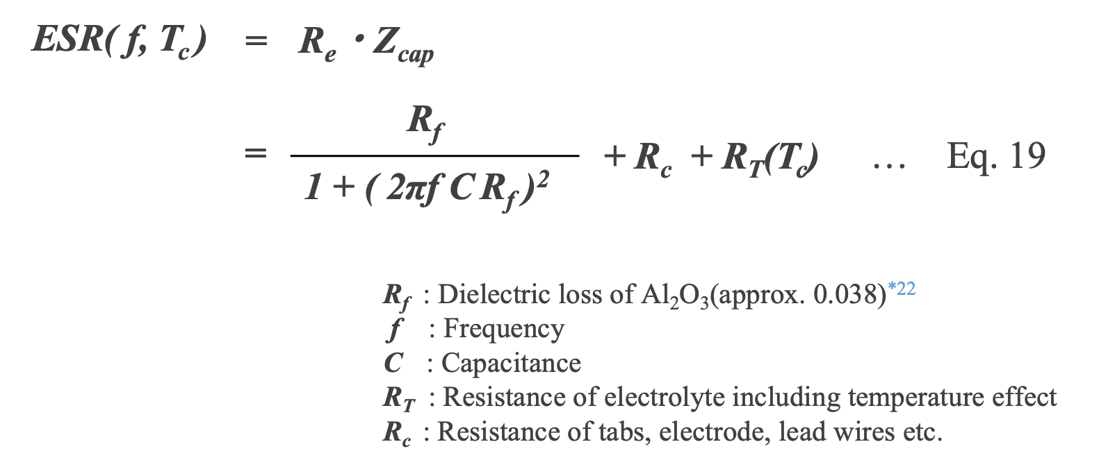
*21 F. Hayatee, “The equivalent series resistance in electrolytic capacitors," Electrocomponent Science and Technology, vol. 2, pp. 67-72, 1975. [111]
*22 Rf is the resistance due to the alignment of dipoles in the dielectric oxide during voltage reversal.
M. L. Gasperi, \A method for predicting the expected life of bus capacitors," in Conference Record of the 1997 IEEE Industry Applications Conference (IAS 1997), 1997,pp. 1042-1047. [112]
Al-Ecap ESR is extremely sensitive to the viscosity and conductivity of the electrolyte*23. The lower the viscosity of the electrolyte, the easier it penetrates the anode and separator paper, increasing conductivity and reducing ESR. At lower temperatures, viscosity increases, conductivity decreases, and ESR increases. The conductivity of an electrolyte depends on the ionic radius of the solvent and solute in the electrolyte, but the ESR can be 10 to 100 times greater than at room temperature.
The temperature dependence of Al-Ecap ESR contained in RT is due to viscosity change of the electrolyte Eq.20 *24. This change in viscosity changes ion mobility and electrolyte resistance.

*23 The conductivity of an electrolyte is determined by its concentration and viscosity. Electrolytes with high solubility and high ionization will have a high charge density. Solvents with small viscosity η 〔Pa・s〕and electrolytes with small ionic radius have larger mobility μ 〔m2/V・s〕.
*24 Rf Determining End-of-life, ESR, and Lifetime Calculations for Electrolytic Capacitors at Higher Temperatures, Aug. 2008. [113]
Thermal resistance Rth
The final component needed to calculate the ripple voltage acceleration factor is the thermal resistance (Rth) of the capacitor. The value of Rth determines how quickly a capacitor may dissipate heat to lower Tc towards Ta. Rth is simply the reciprocal of the total heat transfer coefficient, Htotal, and the surface area (A) of the capacitor (Eq. 21).

As shown in Fig. 4, the internal temperature of a capacitor depends on three modes of heat dissipation, convection, radiation, and conduction. The total heat transfer coefficient Htotal is the sum of the respective heat transfer coefficients (Eq. 22)

Convection is the transfer of heat from the capacitor to a fluid (usually air, though possibly some other cooling liquid). Radiation is heat transfer from the capacitor through the emission of electromagnetic (i.e. infrared) radiation. Conduction is the transfer of heat through contact with a solid material in physical contact with the capacitor (Fig. 4). Conduction usually occurs primarily through the capacitor connection to the exterior mount or a heat sink. This heat transfer mode is usually only a significant portion of the total heat dissipation for small Al-Ecaps, Al-Ecaps with a heat sink attachment, or liquid cooled capacitors. The heat transfer in the capacitor generated by the ripple current is convection and radiation. For this reason, it is important to estimate Hconv and Hrad in Eq. 22.
The main parameters of Hconv include the number (mounting density) and diameter of capacitors, air velocity for air cooling, surface temperature Ts and ambient air temperature Ta. The main parameters of Hrad include surface temperature Ts and ambient air temperature Ta, surface area and emissivity of the capacitor housing.
The above is the basis for a more precise estimation of the effect of ripple current on capacitor heating and lifetime,
- Frequency and temperature dependence of ESR
- Thermal resistance (Rth)
- Heat transfer coefficients of convection and radiation (Hconv and Hrad)
, etc. must be properly understood.
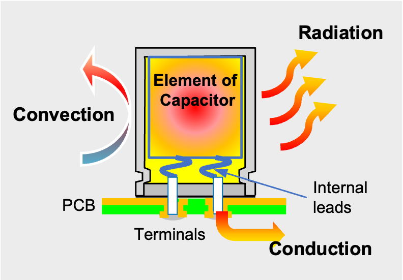
Diagram of convection, radiation, conduction
Lifetime Estimation Formula for Al-Ecap
From the previous discussion, considering the effects of temperature, voltage, and ripple current factors on the lifetime of Al-Ecap, the following Eq. 23 for lifetime estimation can be given.
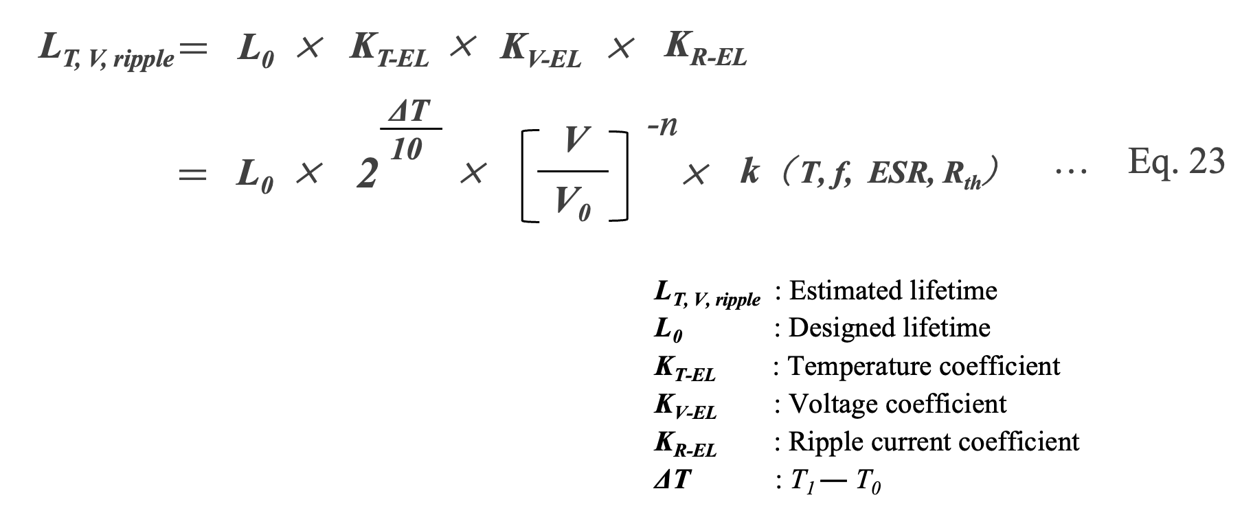
We use Eq. 24 as the standard lifetime estimation formula, which uses the 10°C times 2 law of temperature for KT-EL and the 2.5 power law of voltage for KT-EL. The temperature rise due to ripple current is included in ΔT.

Lifetime Estimation of MF-caps
In the lifetime estimation of MF-cap, accelerated tests are conducted for 2,000 to 3,000 hours at a higher voltage and temperature than rated, and the estimated lifetime is calculated based on the test results when the capacitor is operated at a lower temperature and voltage (derating) than rated.
Each manufacturer discloses it as an expected lifetime of approximately 100,000 to 150,000 hours (about 11 to 15 years) *25. In other words, most lifetime expectancy and acceleration rate formulas from various manufacturers are not theoretically derived, but rather empirically derived in accordance with experimental data. Furthermore, MF-caps have a self-healing property (SH) not found in other capacitors, and its performance varies from manufacturer to manufacturer. For this reason, care must be taken when applying one manufacturer's acceleration factor to another.
*25 “Capacitors Age and Capacitors Have an End of Life," Emerson Network Power, Tech. Rep., Aug. 2008. [117]
As mentioned earlier, a common failure mode for MF-caps is a reduction in capacity due to a number of small SHs. The number of occurrences of this event increases with time*26 and the rate of change in capacitance depends on temperature, voltage, and humidity. Therefore, these parameters are acceleration factors that affect the lifetime of the MF-cap. This section explains the concept of these acceleration factors and acceleration coefficients.
*26 J. Zhao and F. Liu, “Reliability assessment of the metallized film capacitors from degradation data," Microelectronics and Reliability, vol. 47, no. 2-3, pp. 434{436, Feb.2007. [65]
Temperature-accelerated factor KT-MFC
It is shown that in MF-cap as well as Al-Ecap, the lifetime becomes shorter as the temperature increases, and the temperature dependence of the lifetime follows the Arrhenius law*27 (Eq. 25).
*27 Q. Sun, et. al, “Reliability assessment of metallized film capacitors using reduced degradation test sample,” J. Qual. Eng. Int., vol. 29, no. 2, pp. 259–265, Mar. 2013. [14]

For the acceleration factor KT-MFC derived from the Arrhenius law, the “10°C doubling rule” is used, but there is also a theory that proposes the “8°C doubling rule” which states that the lifetime is halved for every 8°C above the rated temperature (Eq. 26) *28.
*28 W. Sarjeant, J. Zirnheld, and F. MacDougall, “Capacitors," IEEE Transactions on Plasma Science, vol. 26, no. 5, pp. 1368{1392, 1998. [39]

Voltage acceleration factor KV-MFC
When operated in a constant voltage mode, the capacitance of MF-caps deteriorates and MF-caps have significantly shorter lifetimes because of frequent SH events. MF-caps which have long lifetimes for pulsed applications would be expected to have much shorter lifetimes under constant voltage conditions*29, 30.
Lifetime calculations must include some voltage multiplication factor, as lifetime decreases rapidly as DC voltage approaches rated voltage. The voltage acceleration factor KV-MFC depends on the quality, manufacturing method, and type of capacitor, but is expressed by Eq. 27, where n is typically in the range of 10 to 20*30, 31s. This very large voltage acceleration factor means that voltage rating of MF-cap is of primary importance, since any over-voltage can have drastic deleterious effects on capacitor lifetime.
*29 H. Fuhrmann, et al., ”Novel Measurement Methods for In-depth Analysis of AC Metallized Film Capacitors," in IEEE International Symposium on Electrical Insulation, 2004, pp. 568-571. [119]
*30 W. Sarjeant, et al., “Energy storage capacitors: Aging, and diagnostic approaches for life validation," in IEEE Transactions on Magnetics. Aerovox Inc, New Bedford, Ma, 1997, pp. 501-506. [91]
*31 T. Umemura, et al., “Accelerated-life Testing of Power Capacitor Dielectric Systems," IEEE Transactions on Electrical Insulation,, no. 3, pp. 309-316, 1987.[121]

Humidity acceleration factor KRH-MFC
Plastic film has the property of permeating and absorbing moisture. If moisture remains inside the MF-cap or penetrates from the outside, the film's insulating properties will deteriorate and the deposited electrode, which is less than 20 to 100 nm thick, will detach or corrode. In addition, the dipoles of water molecules increase the loss factor of the MF-cap and decrease its insulation resistance, eventually leading to catastrophic failure*32. This causes gas to be generated and the metalized layers to become insulated, resulting in failure. Eq. 28 shows the reaction equation in the case of aluminum metallization*33.
*32 Brown R. W. “Linking Corrosion and Catastrophic Failure in Low-Power Metallized Polypropylene Capacitors.” IEEE Transactions on Device and Materials Reliability Vol. 6 No. 2 (2006): pp. 326-333. [17]
*33 Anodic oxidation reaction of aluminum metalized electrode under high temperature, high humidity biased condition

Fig. 5 shows the outlooking (left) and X-ray CT image (right) of a MF-cap that failed in a high temperature, high humidity bias test (THB). The current and moisture corroded the metalized electrode, causing the film to decompose and generate gas. The gas pressure made the resin case swell, and the outer layer of the capacitor's wound element was observed to be damaged.
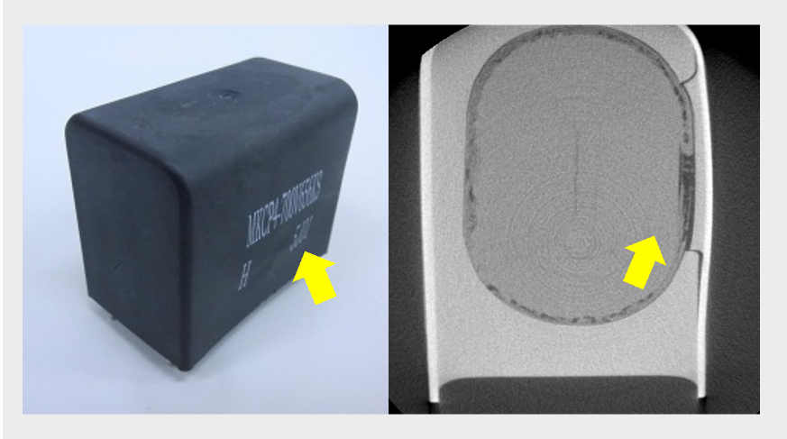
Outlook and X-ray CT image of Failure capacitor by THB test
AICtech Type MKCP4 700V 80μF
Zhuai et al. evaluated the magnitude of capacitance change of MF-cap with respect to relative humidity and noted humidity acceleration (Fig. 6) *34.
*34 Shuai Zhao a, Shaowei Chen b, Huai Wang, “Degradation modeling for reliability estimation of DC film capacitors subject to humidity acceleration” Microelectronics Reliability Vol 100–101, September 2019, 113401
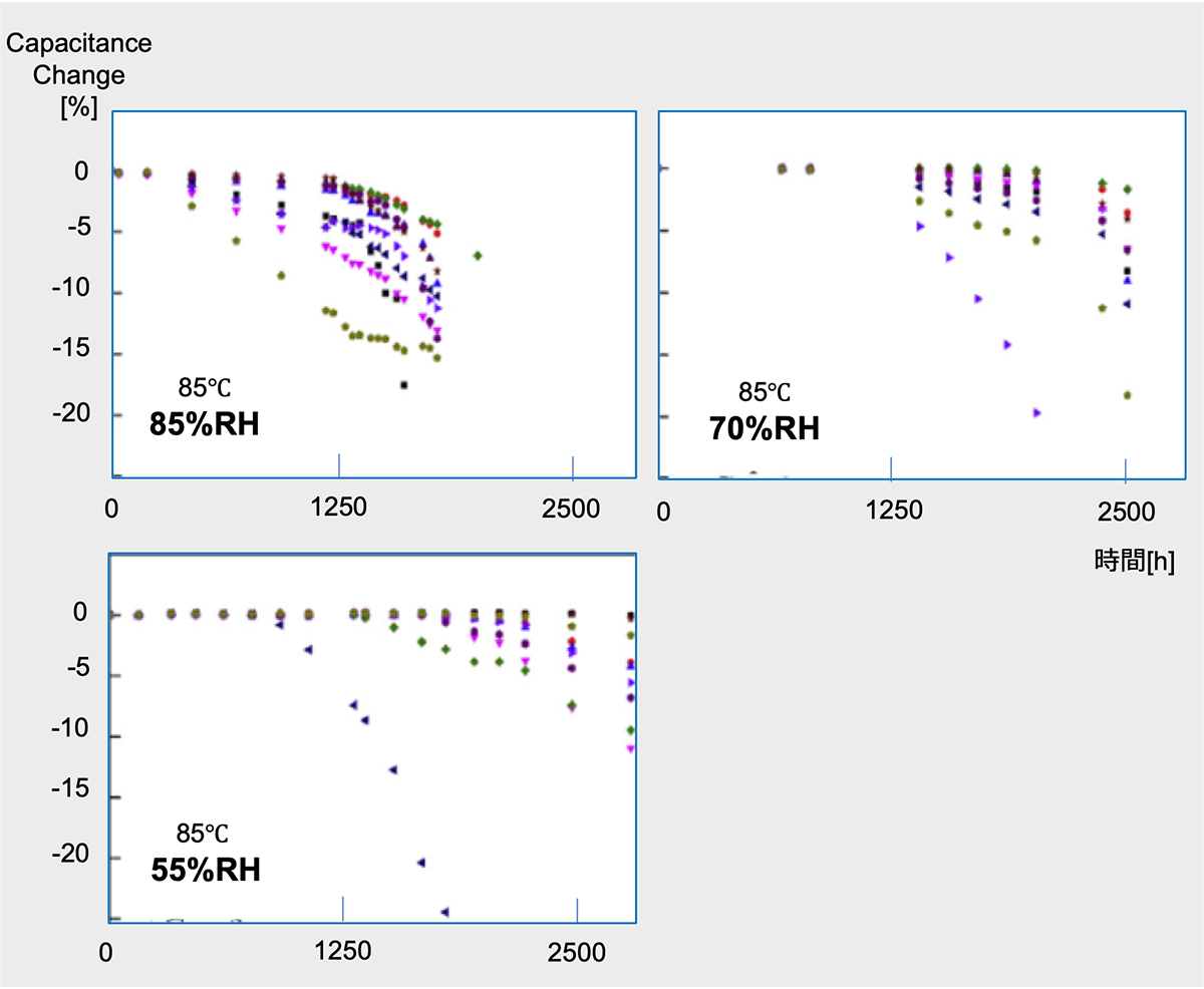
Capacitance chage of MF-cap at THB test
(Resin box type1100V 40μF)
The effect of humidity on lifetime can be estimated using Eq. 29, called the Hallberg-Peck rule*35, where RH0 is the reference humidity.
*35 Ö. Hallberg and D.S. Peck, Qual. Reliab. Eng. Int. 7 (1991) 169.

Tai et al. demonstrated from accelerated aging tests of MF-cap under high temperature and high humidity conditions and failure mechanism analysis that under high humidity (>69% relative humidity) operating conditions, water molecules and oxygen cause electrochemical corrosion and damage the metalized layer, consisting of aluminum, zinc, etc., on the capacitor film. Furthermore, a lifetime estimation model has been established and the activation energy of failure, Ea = 1.48eV, and the coefficient of humidity failure, m, has been calculated to be 4*36. Improving the moisture resistance of MF-caps is a key to expanding the applications of these capacitors. In recent years, products that can guarantee a 85°C 85% bias load for 1000 hours (THB : Thermal Humidity Bias Test *37 ) have also been developed.
*36 https://www.sciencedirect.com/science/article/abs/pii/S0026271422002797
*37 Thermal Humidity Bias Test
Notices of temperature and voltage
As in Al-Ecaps, ripple current increases MF-cap core temperature due to resistive heating. The core temperature TC can be approximated by Eq.30 using the ambient temperature Ta, dielectric loss Pd, thermal loss Pt and thermal resistance Rth of the capacitor. Since TC is directly related to MF-cap lifetime, TC should be set lower than the rated temperature.

Dielectric loss Pd, represents as Eq.31, is due to energy absorption by the polymer dielectric medium from the rearrangement of dipoles at a frequency, f.

*38 G. Buiatti, S. Cruz, and A. Cardoso, “Lifetime of film capacitors in single-phase regenerative induction motor drives," IEEE International Symposium on Diagnostics for Electric Machines, Power Electronics and Drives, 2007 (SDEMPED 2007), pp.356-362, 2007. [66]
Thermal power loss Pt is due to joule heating of the capacitor as shown in Eq. 32.

Since the operating voltage VW is the sum of the dc voltage and the ripple voltage (Eq. 33). MF-cap with a voltage rating higher than the operating voltage must be selected and used.

Lifetime estimation equation for MF-cap
From the previous discussion, it is considered that the factors of temperature, voltage, and humidity have a significant effect on the life of MF-cap, so the life estimation formula for MF-cap can be expressed as the following Eq. 34.

However, to use this equation, it is necessary to design experiments at different temperature, voltage, and humidity levels and conduct evaluation tests to determine the activation energy Ea, voltage acceleration factor n, and humidity acceleration factor m with respect to the temperature dependence of failure.
Although MF-cap has less self-heating due to ripple current than Al-Ecap, it is characterized by a tendency to deteriorate due to humidity. For this reason, a life estimation formula (Eq. 35) has been proposed that takes into account degradation due to humidity as well as temperature and voltage*39.

*39 Huai Wang, et.a al., “Reliability of Capacitors for DC-Link Applications in Power Electronic Converters, An Overview” IEEE Transactions on Industry Application, Vol. 50, NO. 5, 2014
It is also important to estimate MF-cap lifetime under conditions that more closely resemble actual applications. For example, in the operation of a solar inverter, there are 50% of the time when the no voltage is loaded and the temperature is 20°C, 20% of the time when the voltage is maximum and the temperature reaches 90°C, and 30% of the time when the voltage is maximum and the temperature is 60°C. By converting each operating condition into three parameters, a practical expected lifetime can be obtained.
As mentioned earlier, the lifetime estimation of MF-cap is not theoretically derived, but rather empirically derived in accordance with experimental data. So, every manufacturer offers an original lifetime estimation formula. This reason is that the chemical properties of the materials used, the capacitor topology, and the testing methods and procedures may differ from manufacturer to manufacturer. Care should be taken when applying one manufacturer's lifetime estimation formula to another manufacturer's product, so we recommend counseling with the manufacturer before use.
Lifetime Estimation of MLCC
The parameter of note in degradation failures of MLCCs is capacitance. MLCCs have a tendency for capacitance degradation during use according to Eq. 36 *40

*40 W. Mason, “Aging of the properties of barium titanate and related ferroelectric ceramics," Journal of the Acoustical Society of America, vol. 27, no. 1, pp. 73-85, 1955. [126]
*41 I. Burn, Ceramics and Glasses, S. Schneider, Ed. ASTM, 1991, vol. 4. [127]
This aging is due to the ferroelectric and volumetric response of the ceramic upon cooling from the Curie Temperature*42. The capacitance of an MLCC can be restored by heating above the Curie Temperature for 1-4 hours. MLCC manufacturers frequently add doping materials to the ceramic in order to lower the Curie Temperature and facilitate “de-aging" of the capacitor by heating.
*42 The Curie temperature is the temperature at which ferromagnetic materials become paramagnetic. At this point, the thermal energy overcomes the attraction between the magnetic moments of the domains and the magnetic spins become random within the material.
Much like other capacitors, MLCCs have a voltage dependent lifetime acceleration. This degradation is due to Poole-Frenkel emission which leads to avalanche breakdown*43, 44. The lifetime of the capacitor is inversely related to the applied voltage raised to the power and is highly dependent on ceramic type and morphology. For example, delamination, cracks, voids, pores, etc. may result in local electric fields much larger than the average.
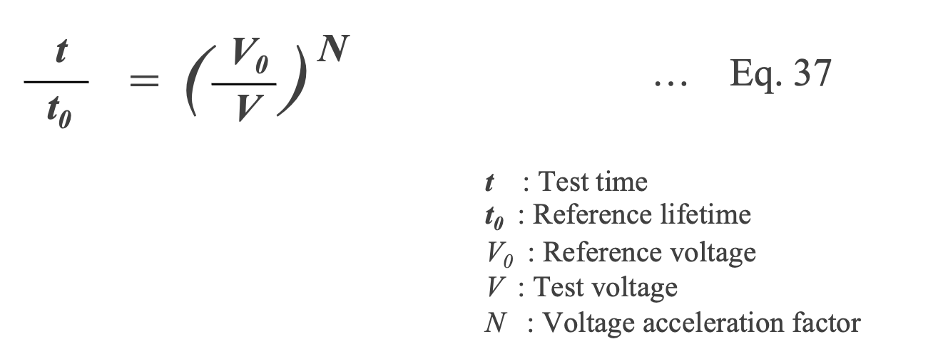
In the voltage acceleration test of MLCCs, the relationship between the time at which a failure occurs, t, and the applied voltage, V, is expressed by Eq.37. For example, N =2.6 for V=50-150V across a 2.5×10⁻³cm BaTiO3 dielectric*45. The value of N drops to 1.2 for the same dielectric with thicker dielectric layers due to the reduction of the average internal electric field*40. The factor N of 1 to 3 are generally used.
*43 B. Rawal et. al., “Conduction and failure mechanisms in barium titanate based ceramics under highly accelerated conditions," in Proceedings of the 34th Electronic Components Conference, 1984, pp. 184-188. [99]
*44 E. Loh, “Development of a model for voltage degradation of various dielectric materials," IEEE Transactions on Components, Hybrids, and Manufacturing Technology, vol. 4, pp. 536-544, 1981.[128]
*45 J. Minford et. al.,” Accelerated aging study of multilayer ceramic capacitors," in American Ceramic Society Annual Meeting, Cincinnati, Ohio, 1979. [129]
This voltage accelerated lifetime does not account for any temperature dependent effects. An increase in leakage current under increased temperature is generally due to thermal runaway. This thermal runaway is generally caused by intrinsic factors (i.e. electronic disorders, dislocations, grain boundaries, etc. ) in the ceramic.
Both avalanche and thermal breakdown are occurring during capacitor operation. The combination of the two breakdown modes can be combined to find an overall lifetime acceleration according to Eq. 38*46.
*46 T. Prokopowicz and A. Vaskas, “Research and development, intrinsic reliability, subminiature ceramic capacitors," Sprague Electric Corporation, Tech. Rep., Oct. 1969. [130]
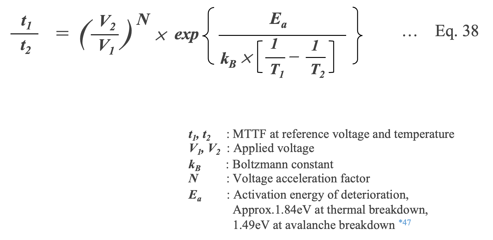
*47 B. Rawal et. al.,“Conduction and failure mechanisms in barium titanate based ceramics under highly accelerated conditions," in Proceedings of the 34th Electronic Components Conference, 1984, pp. 184-188.
This equation has been shown to fit well to data for high quality MLCCs under JIS and MIL-STD testing conditions (CR>20 MF with 200% rated voltage at 85℃ for 1000 hours) *48, 49.
*48 W. Minford, “Accelerated life testing and reliability of high-k multilayer ceramic capacitors," IEEE Transactions on Components, Hybrids, and Manufacturing Technology, vol. 5, no. 3, pp. 297-300, 1982.[131]
*49 R. Munikoti and P. Dhar, “Highly accelerated life testing (halt) for multilayer ceramic capacitor qualification,“ IEEE Transactions on Components, Hybrids, and Manufacturing Technology, vol. 11, no. 4, pp. 342-345, 1988. [132]
Lifetime Parameters
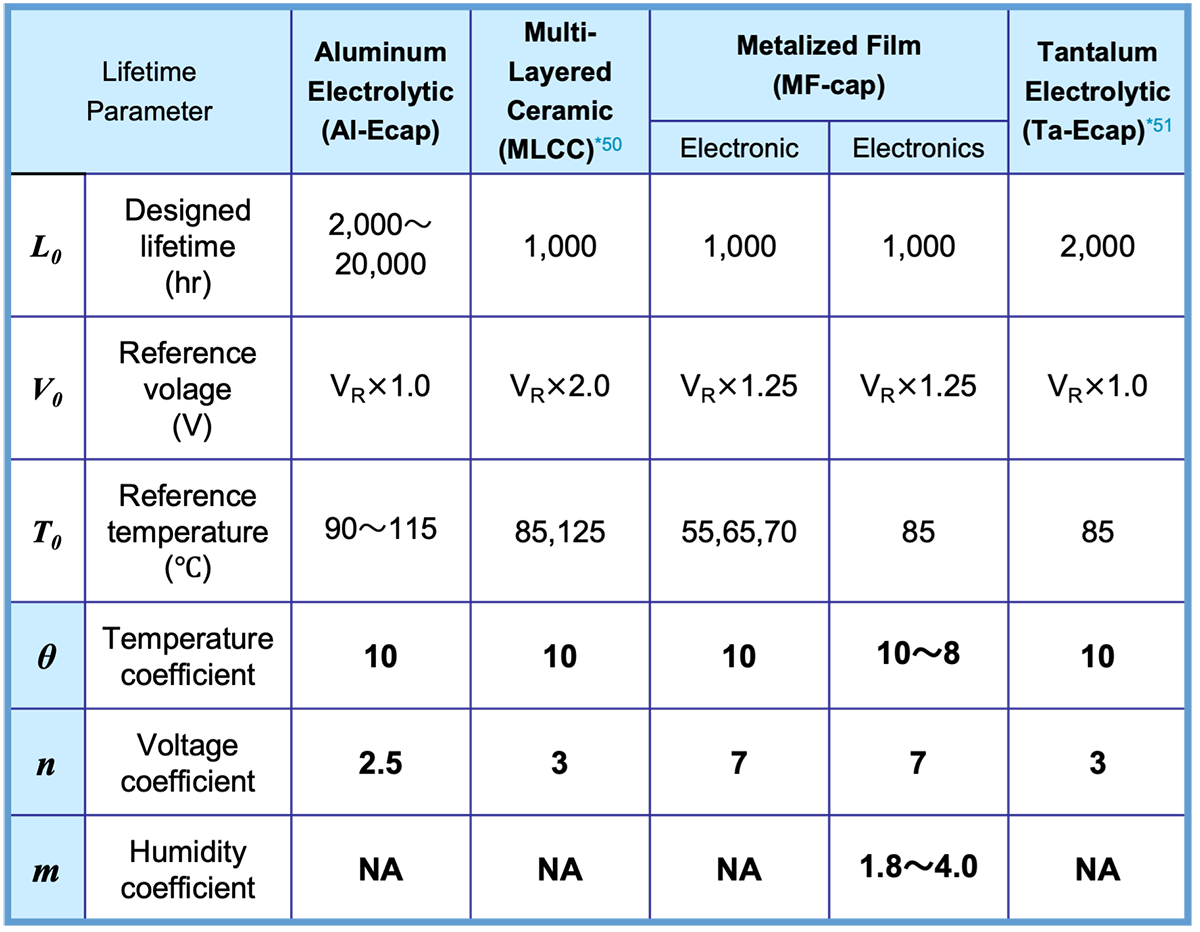
Experimental formulas are used to estimate the life of capacitors with temperature and voltage as parameters; for MF-cap, humidity is also a parameter. However, the magnitude of the effect of these parameters on capacitor life (acceleration factor) depends on the capacitor type. To determine the acceleration factors, life tests are conducted for each capacitor at various temperatures, voltages, and humidity conditions. The activation energy Ea for each parameter is obtained from the evaluation tests, and the temperature acceleration factor θ, voltage acceleration factor n, and humidity acceleration factor m are determined.
Table 1 summarizes the parameters and coefficients for life estimation for each capacitor.
*50 Jung-Rag Yoon and Kyung-Min Lee, “Analysis the Reliability of Multilayer Ceramic Capacitor with inner Ni Electrode under highly Accelerated Life Test Conditions”, TRANSACTIONS ON ELECTRICAL AND ELECTRONIC MATERIALS VOL. 10, NO. 1, FEBRUARY 25, 2009
*51 https://nepp.nasa.gov/files/24717/Teverovsky_2013_n258_VoltageAcceleration_CPMT_pres.pdf
A note on the use of acceleration coefficients
In general, the 10°C double rule is used to express the relationship between temperature and life, but this rule does not always hold true for temperatures near practical use, such as 50-60°C, or beyond the maximum operating temperature. However, this rule does not necessarily apply to temperatures in the vicinity of the operating temperature range, such as 50-60°C, or temperatures above the maximum operating temperature, and MF-cap may suggest the 8°C double rule, which states that the life is halved for every 8°C above the rated temperature.
The scope of application and the suitability of the temperature acceleration rule should be checked with the manufacturer.
The relationship between voltage and life should also be noted. We have assumed a voltage acceleration factor of 2.5 for Al-cap. However, the voltage acceleration factor varies between 2 and 5 depending on the manufacturer and the type of capacitor (e.g., solid electrolyte type, electrolyte type, etc.).
We use a voltage acceleration factor of 7 for MF-caps, but values of 10 to 20 may be used depending on the type and thickness of the dielectric. 1.8 to 4 is often reported for the humidity acceleration factor of MF-caps as explained in section 3.3 (section 3) *52, 53.
*52 https://www.reaj.jp/pdf/event/2021/0531-1-1.pdf
*51 Huai Wang., “Capacitor Failure Modes and Lifetime Models from an Application Perspective”, PSMA and PELS Capacitor Workshop 2018

Editorial supervision/Kazuyuki Iida
General Advisor, AIC tech Inc.
Born in the Tokyo area in 1956
M.S. of Sc, Sophia University, Tokyo, Japan. 1982
Over 35 years experience with knowledge on capacitor technology, i.e. R&D for high-performance capacitor and its materials, marketing activities at Hitachi Chemical Co, Ltd. and Hitachi AIC Inc. and Contributed articles on capacitors to public relations magazines, trade journals, and various handbooks.
Instructor of capacitor technology at the Technical Training Institute of Hitachi, Ltd. from 2005 to 2015.
General advisor to AIC tech Inc. from 2020.
- "Tantalum Electrolytic Capacitor"
The Electrochemical Society of Japan (ed.) Maruzen Handbook of Electrochemistry, 5th Edition, Chapter 15, Capacitors, Section 15.2.4 b (1998) - "Development Trend and Material Technology of Tantalum-Niobium Capacitors"
Technical Information Association of Japan Seminar June 2008 - Lead-Free Surface Mount Film Capacitors MMX-EC, MML-EC Series
Hitachi Chemical Technical ReportNo. 48. Product Introduction 2007 - "Film Capacitors for Electronic Devices"
Maruzen Capacitor Handbook, 5th Edition, Chapter 5, Film Capacitors, Section 5.2 (2009). - "Film capacitor MLC series for new energy"
Shinkobe Electric Co., Ltd. Shinkobe Technical Report Np. 22 (2012).
PDF Download
