Capacitor Failure Modes and Lifetime
(MLCC, Tantalum Capacitors & More)
Contents
Failure Modes and Mechanisms
Differences Between Failure Modes and Mechanisms
Failure modes is the result, failure mechanism is the process
A failure mode is any event (result) of a failure. Failures are classified into catastrophic failures (complete loss of function) and degradation failures (out of tolerance). Failure mechanism is a process that leads to failure due to various causes such as electrical, physical, mechanical, chemical, etc.
It is important to note that even if the failure mode (result) is the same, the failure mechanism (process) may be completely different, and even if the failure mode is the same, there may be many different failure mechanisms. Even if the failure mechanism is the same, different failure modes may result. For example, the capacitance degradation failure follows different failure mechanisms for aluminum electrolytic capacitors and film capacitors. Electromigration is one of failure mechanisms of semiconductor, but the failure mode can appear as a short, open, or characteristic degradation.
Failure Modes and Mechanisms of Capacitors
Capacitors have several failure modes, the degree of which depends on the type of capacitor (Table 1).
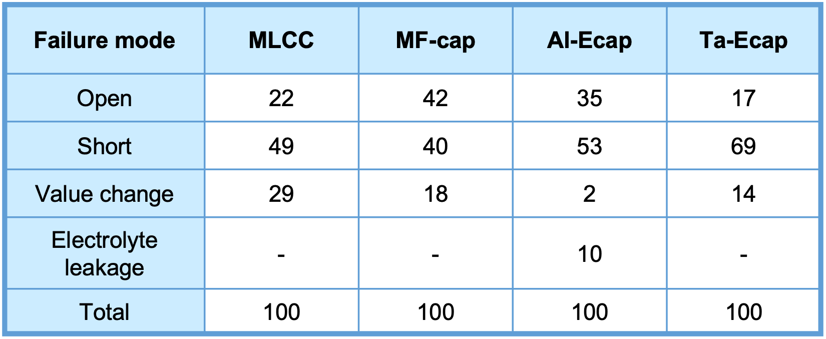
*01 IIT Research Institute, Failure Mode, Effects and Criticality Analysis (FMECA) , 1993 IIT : Illinois Institute of Technology
Capacitors have several failure modes, and which failure mode is more or less common depends on the type of capacitor (Table 1). Capacitor failures can be described by two basic failure categories: catastrophic failures and degraded failures. Catastrophic failure is the complete loss of function of the capacitor in a circuit.
Catastrophic failure, such as open or short circuit, is the complete loss of function of the capacitor. This failure can cause the enclosure to explode, smoke, ignite, harm other electrical components, or leak liquid or gas from inside the capacitor. Degradation failures may include increased leakage current, increased ESR, and decreased capacitance, although the definition of parameters and their limits vary among manufacturers*02, 03.
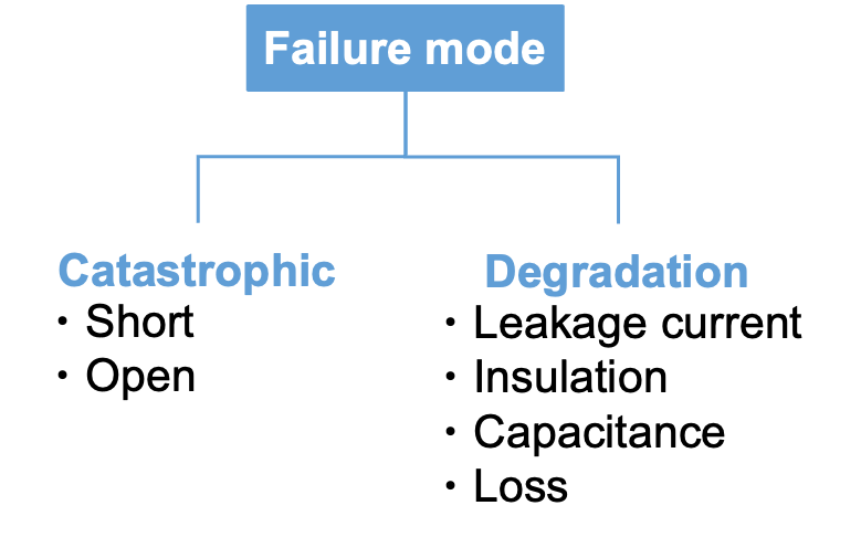
Capacitor failure modes
*02 W. Sarjeant, et.al., “Capacitors,” IEEE Transactions on Plasma Science”, vol. 26, no. 5, pp.1368-1392, 1998. [39]
*03 D. Guo, “Wear analysis and degradation mechanism of film metallized capacitor,” Power Capacitor (China), vol. 2, pp. 12-15, 1995. [87]
Reaction Theory Models for Capacitor Failure Mechanisms
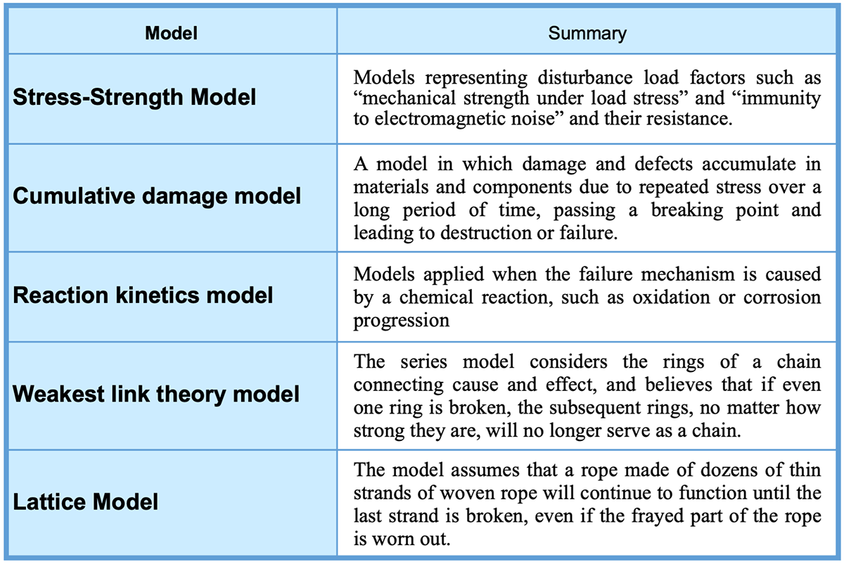
In the Physics of failure or Reliability physics, which is the basis of reliability engineering, the five failure models shown in Table 2 are used to model the processes leading to failure*04.
*04 H. Shiomi, Japanese Journal of Applied Physics vol. 95 (6) pp. 559-564 (1976)
Since chemical reactions such as corrosion and oxidation often lead to capacitor failures, failure analysis and reliability design are commonly conducted by applying the kinetics model (Figure 2). In particular, the Arrhenius model is used for temperature acceleration, in which degradation progresses as temperature rises, and the θ °C law is used as an empirical law. The 10°C rule, which means the capacitor's life doubles for every 10 degree Celsius decrease in temperature is often used for lifetime estimation.
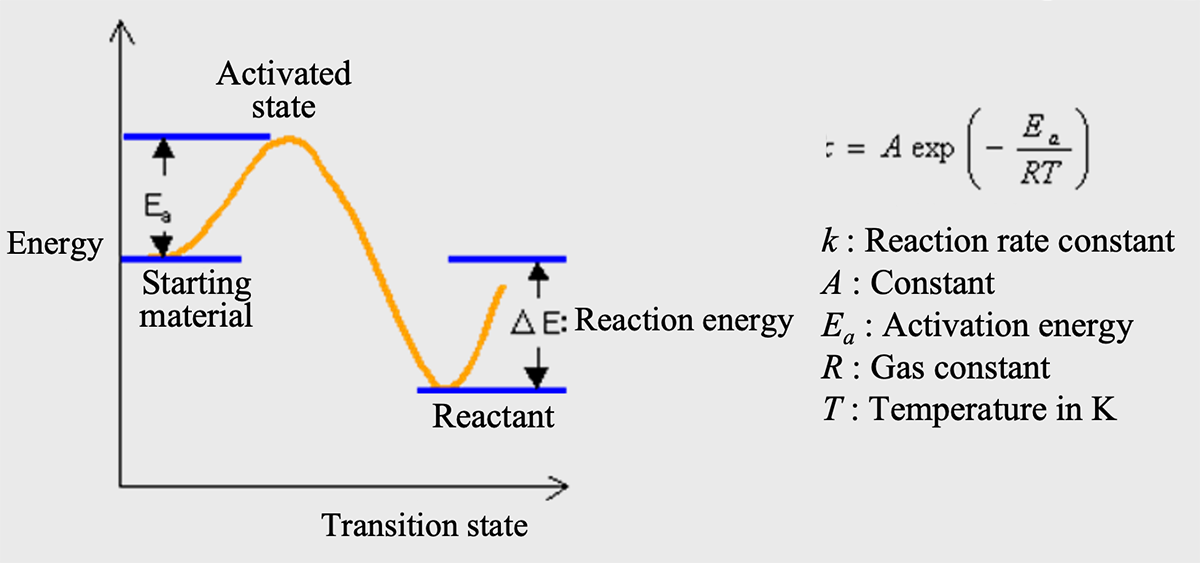
Conceptual diagram of chemical kinetics model*05
*05 A material transits to an activated or degraded state when it gains energy from outside. This energy is called activation energy.
When this is applied to failure or degradation analysis, an accelerated life test is performed to determine the activation energy.
Failures of Al-Ecap
Al-Ecap offers excellent cost performance with high capacitance per unit volume due to its unique electrode with a porous material with a large surface area and a thin dielectric with a high relative permittivity. The primary roles of an Al-Ecaps in circuits are to smooth ripple voltages and act as an energy buffer to supply electrical energy in a moment.
However, when used under conditions of high electrical or thermal stress, Al-Ecap can fail in a shorter time than other components. Specifically, Al-Ecap experiences a decrease in capacitance and an increase in ESR; the IEC and other standards set limits for changes in each parameter, and define end-of-life as the time when these values are exceeded. In some cases, the lifetime is defined by the magnitude of electrical and thermal stresses and their combined conditions, as AL-Ecap's characteristics change not only during operation but also due to thermal stresses during storage*06, 07.
*06 [*] MIL-C-62F. “General specification for capacitors." Military Specifications and Standards. 2008.
*07 IEC-60068-1. “Environmental testing, part 1: General and guidance." IEC Standards. 1988.
Physical failure due to high temperature or excessive ripple current
The primary failure mechanism for Al-Ecap is vaporization of the electrolyte through polymer seals due to excessive thermal stress. As the vapor pressure of the electrolyte increases due to high temperatures, the diffusion rate increases. The electrolyte vaporization and diffusions through the encapsulant causes a decrease in capacitance and an increase in ESR. In other words, increases in capacitor temperature due to ambient temperature and ripple current accelerate capacitor wear out. It is a physical failure of AL-Ecap.
Chemical failure due to overvoltage, charging/discharging, etc.
As mentioned above, leakage current through the electrolyte drives the reformation of Al2O3 dielectric through the consumption of H2O in the electrolyte according to Equation (05). However, this reaction leads to the following failure modes*08 to *13.
The first is that reformed oxide is of a poorer quality than the original oxide formed via anodization. The replacement of high quality oxide with poor quality oxide reduce the performance of the AL-Ecap over time.
Secondly, the consumption of H2O leads to higher ESR values from the decreased electrolyte volume.
*08 [21] Kulkarni, C. “A physics-based degradation modeling framework for diagnostic and prognostic studies in electrolytic capacitors.” Ph.D. Dissertation. Vanderbilt University. 2013.
*09 Kulkarni C. et al. "Physics Based Electrolytic Capacitor Degradation Models for Prognostic Studies under Thermal Overstress." 1st European Conference of the Prognostics and Health Management Society. 2012. [22]
*10 Albertsen, A. “Electrolytic Capacitor Lifetime Estimation.” Jianghai. 2010. [23]
*11 Perisse, F. “Etude et analyse des modes de d´efaillances des condensateurs electrolytiques a l’aluminium et des thyristors, appliqu´ees au syst`eme de protection du LHC (Large Hadron Collider).” Master’s thesis. Claude Bernard University. 2003. [24]
*12 Lahyani A. et al. "Failure prediction of electrolytic capacitors during operation of a switch mode power supply." IEEE Transactions on Power Electronics. Vol. 13 No.6 (1998). pp. 1199 – 1207. [25]
*13 Shrivastava A. et al. "Detection of capacitor electrolyte residues with FTIR in failure analysis." Journal of Materials Science: Materials in Electronics Vol. 25 No. 2 (2014): pp. 635 – 645. [26]
Finally, one of the products of the reforming reaction is H2 gas. Since the capacitor can is airtight to prevent evaporation of the electrolyte, H2 gas accumulates inside the canister over time, increasing the interior pressure. Once the interior pressure builds to about 5 atm, the pressure relief vent release, bursting the capacitor can. After the can is exposed to air, the electrolyte readily evaporates and the capacitor fails.
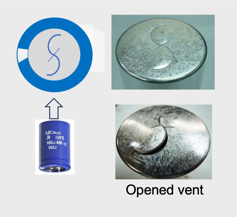
“S” shape pressure relief vent of AIC tech’s snap-in Al-Ecap
When Al-Ecap is loaded with continuous charge-discharge cycles, anodic oxidation reactions that modify Al2O3 are repeated. This can result in a risk of failure. Table 3 summarizes the main causes, failure mechanisms, and failure modes of Al-Ecap failures.
In summary, the life of AL-Ecaps depends on environmental and electrical factors. Environmental factors include temperature, humidity, atmospheric pressure, and vibration. Electrical factors include operating voltage, ripple current, and charge-discharge duty cycle. Because AL-Ecaps are essentially an electrochemical device, increased temperatures accelerate the chemical reaction rates within the capacitor. Temperature (ambient temperature and internal heating resulting from ripple current) is the most critical to the life of AL-Ecaps.
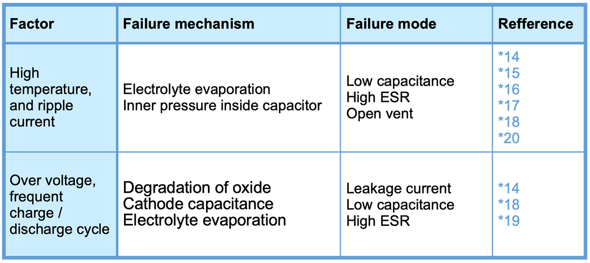
Voltage within the allowed operating range has little effect on the actual life expectancy of a capacitor. If an overvoltage exceeding the rated voltage of the capacitor is applied, the leakage current will increase significantly, resulting in increased heat generation and failure*19.
*14 Kulkarni, C. “A physics-based degradation modeling framework for diagnostic and prognostic studies in electrolytic capacitors.” Ph.D. Dissertation. Vanderbilt University. 2013. [21]
*15 Kulkarni C., Jose C., Biswas G., and Goebel K. "Physics Based Electrolytic Capacitor Degradation Models for Prognostic Studies under Thermal Overstress." 1st European Conference of the Prognostics and Health Management Society. 2012. [22]
*16 Albertsen, A. “Electrolytic Capacitor Lifetime Estimation.” Jianghai. 2010. [23]
*17 Lahyani A., et. al., "Failure prediction of electrolytic capacitors during operation of a switch mode power supply." IEEE Transactions on Power Electronics. Vol. 13 No.6 (1998). pp. 1199 – 1207. [25]
*18 Shrivastava A., et. al., "Detection of capacitor electrolyte residues with FTIR in failure analysis." Journal of Materials Science: Materials in Electronics Vol. 25 No. 2 (2014): pp. 635 – 645. [26]
*19 Imam A. M., et al. “Electrolytic Capacitor Failure Mechanism Due to Inrush Current.” IEEE Industry Applications Annual Meeting: pp.730-736. Sept. 2007. [27]
*20 M. L. Gasperi. "Life prediction model for aluminum electrolytic capacitors." in Industry Applications Conference, 31st IAS Annual Meeting Vol. 3: pp. 1347-1351. 1996. [52]
Failures of MF-cap
Self-healing (SH), the unique abilities of MF-caps.
To consider MF-cap failure modes and failure mechanisms, it is necessary to understand the unique self-healing abilities of MF-caps. Self-healing (SH), also known as clearing is closely related to MF-cap failure and lifetime. If there is a micro-void or defect in the dielectric film and the capacitor is connected to a voltage of a sufficient level (electric-field stress), a glow discharge occurs in the micro-void. This discharge generates heat due to a high current density in the breakdown region, which causes metalized layer around the void. The damaged part is disconnected from the capacitor and cannot degrade its performance.
There are defects in the dielectric film from film micro-voids (air pockets), foreign particles, and non-uniform polymer. The manufacture process for biaxially oriented polypropylene thin film (the most common thin film dielectric) involves extrusion of the polymer feedstock followed by stretching into thin sheets. This manufacturing method introduces oxidation damage and residual stress to the final polymer, causing the dielectric to begin aging relatively early*21. Since the breakdown voltage of the defective area is lower than that of the normal area, a local short circuit occurs in the defective area when the capacitor is operating.
*21 J. Nash, Polymer Engineering and Science, vol. 28, no. 13, pp. 862{870, 1988. [118]
When such a short circuit occurs in a metal foil electrode type film capacitor, the electrodes that sandwich the dielectric come into contact with each other, causing a short circuit and destructive failure of the capacitor. In MF-cap, however, Joule heat is generated by the current flowing through the short-circuited area, which quickly heats the short-circuited area and vaporizes the metalized electrode layer at the short-circuited area. As a result, the short-circuit is isolated from the normal area, and the capacitor continues to function without fatal failure.*22(Fig. 4)
*22 Gebbia, M. “Introduction to Film Capacitors.” Illinois Capacitor, Inc. 2013. [5]
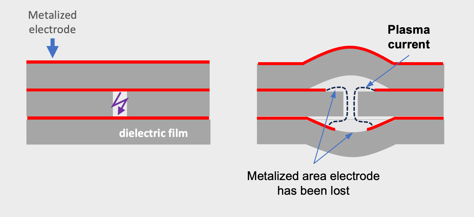
Self-healing mechanism (localized plasma arc)*05
Accumulation of these SH (self-healing) events over time causes self-healing spot (Fig. 5) increases and the capacitance value decreases by a certain percentage of the initial capacitance. As shown in Fig. 6, the capacitance decreases almost linearly with time and eventually drops significantly. This large decrease in capacitance means an increase in SH frequency.
If SH events continue to occur continuously, the capacitor will eventually fail in open mode. However, this failure occurs in a time beyond the manufacturer's estimated lifetime. The definition of failure, i.e., the criteria for capacitance reduction, varies by manufacturer and application. Even if the capacitance decreases, the capacitor can be used safely as long as the insulation of the capacitor itself is maintained. However, if the decrease in capacitance is significant, the circuit may not operate adequately, and the capacitor should be replaced as soon as possible*23.
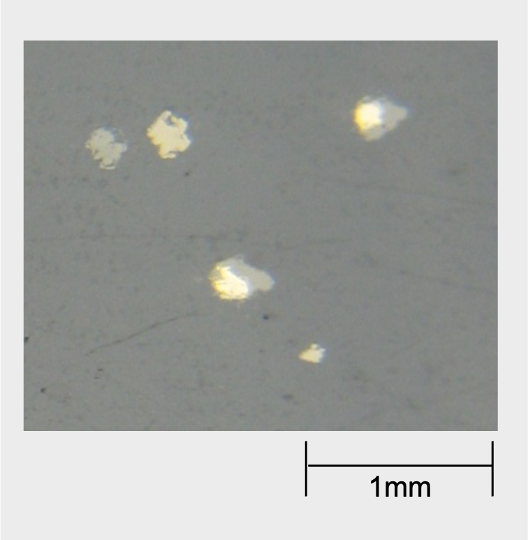
Self-healing spots on metalized film surface
*23 Note that if the capacitor is used for a long time without replacement, the buildup of gases due to the SH phenomenon may lead to fatal failures. Details are explained on the next page.
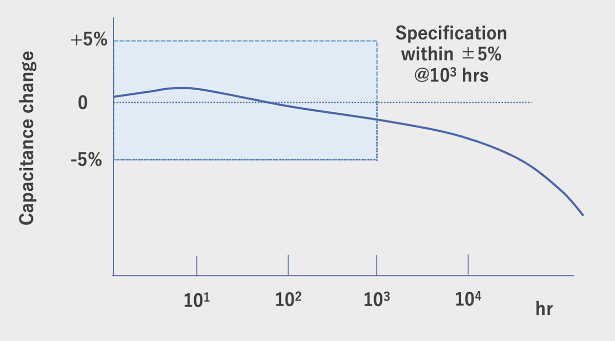
Capacitance decline at high temperature loaded life test of MF-cap
(Our type MLC, rated voltage loaded under 70℃ )
SH factors
The SH events in MF-caps depend on many factors, namely, applied voltage, temperature, air-gap between the winding film layers (or adhesion between film layers), size of the defect area and metallization thickness (resistivity). (Fig. 7)*24.
*24 Qin, S., et al., “The Mechanism of Clearing in Metalized Film Capacitors.” IEEE International Symposium on Electrical Insulation: pp. 592-595. June 2012.[6]
When these factors in Fig. 7 are in balance, SH events work properly and prevent catastrophic failure of the MF-cap. As shown in Fig. 8, the voltage and current condition under SH events appear are limited, and if an excessive voltage beyond this range is applied or a large current flows into the defective area, dielectric breakdown may occur, leading to catastrophic failure of the capacitor.
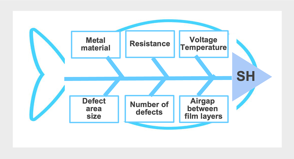
SH factors (Fish bone chart)
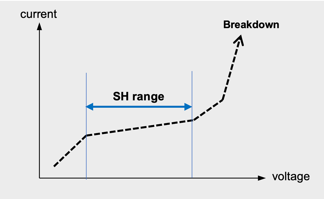
Relationship between the voltage and current flowing in the defect and the image of the range in which self-healing occurs.
SH events are not a universal safety measure and can cause malfunctions.
During SH events, joule heating from the localized discharge vaporizes a certain volume of metallized electrode*25. This discharge creates a localized plasma that interacts with the polymer surface, creating low molecular weight species from the degradation of polymer.
Polymers which are rich in oxygen, namely PET (Polyethylene terephthalate), tend to form CO upon vaporization. Polymers which have a relatively low oxygen composition , namely PP (Polypropylene), tend to form conductive graphitic laments which are more likely to bridge opposing electrodes and form shorts. Low oxygen component polymers are said to be poor clearing polymers and are more likely to clear incorrectly, shorting the electrodes and catastrophically failing*26.
*25 Vaporized gas volume is proportional to the applied voltage.
B. Walgenwitz, et al., “Self-healing of metallized polymer films of different nature,” in Proceedings of the 2004 IEEE International Conference on Solid Dielectrics (ICSD 2004), vol. 1, 2004, pp. 29-32.
*26 C. W. Reed and S. W. Cichanowskil, ”The fundamentals of aging in hv polymer-film capacitors," IEEE Transactions on Dielectrics and Electrical Insulation, vol. 1, no. 5, pp. 904-922, 1994. [64]
As more SH events occur, the production of gas increases pressure inside the case. Excess gas can also lead to can rupture and the gas may be dense enough to conduct charge between electrodes in a process known as flashover (Fig. 2-09, also a catastrophic failure) *27, 28.
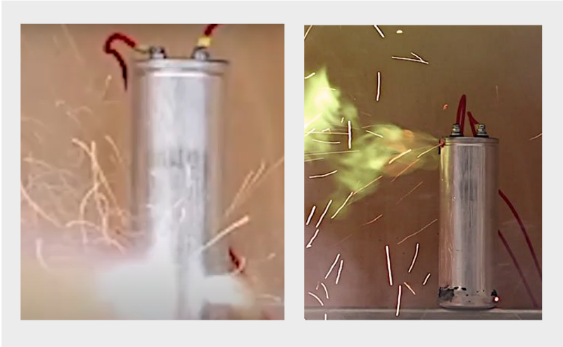
Flashover
https://centiel.co.uk/when-capacitors-fail-they-fail-spectacularly/
*27 Flicker, J., et al. “Lifetime Testing of Metallized Thin Film Capacitors for Inverter Applications.” IEEE 39th Photovoltaic Specialists Conference: pp. 3340-3342. June 2013. [7]
*28 Schneuwly, A, et al. “Uncoupling Behavior of Current Gates in Self-Healing Capacitors." Materials Science & Engineering B Vol. 55 No. 3 (1998): pp. 210-220. [8]
Also, frequent SH events, the production of gas increases pressure inside the case. The gas pressure tends to increase the degradation risk*29 via surface erosion, tracking, and polymer decomposition. This means that localized failure in one area leaves neighboring areas ripe for further electrical breakdown (Fig. 10)*26.
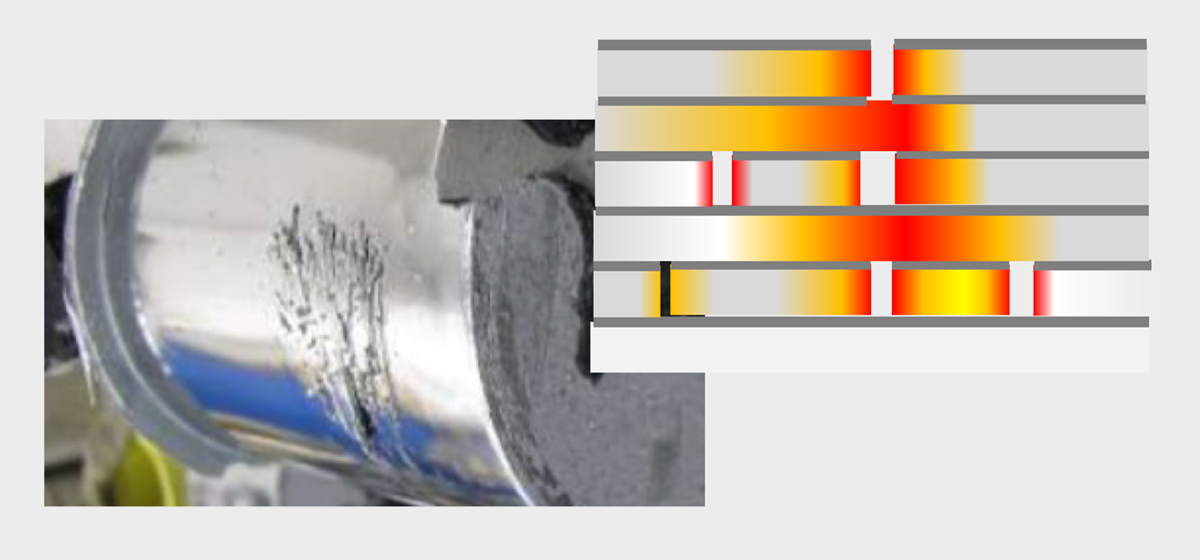
Image of MF-cap element eroded by heat generation due to frequent and repetition of SH
*29 W. Sarjeant, J. Zirnheld, and F. MacDougall, \Capacitors," IEEE Transactions on Plasma Science, vol. 26, no. 5, pp. 1368{1392, 1998.[39]
Factors affecting MF-cap failure and life
Voltage and temperature
Upon an increase in the applied voltage, SH event time take longer, and the heat generated by SH events does not stay localized, but raises the temperature of dielectric film layers in close proximity*30. Once SH event occurs, the energy previously stored in the capacitor is discharged. SH at high temperatures also causes thermal expansion of the dielectric film, increasing the volume of the capacitor element. Hence, It has been pointed out that the difference in thermal expansion coefficients between the dielectric film and the metalized layer causes thermal stress, resulting in a decrease in capacitance, a decrease in insulation properties, and a significant increase in leakage current *31.
*30 Li, H., et al., “Temperature dependence of self-healing characteristics of metallized polypropylene film.” Microelectronics Reliability Vol. 55 No. 12 (2015): pp. 2721-2726. [10]
*31 Mach, P., et al., “Thermal Ageing of Polypropylene Film Capacitors.” 38th International Spring Seminar on Electronics Technology: pp. 272-276. May 2015. [11]
Ripple current
Ripple current is another major stressor on the MF-cap. Ripple current raises the temperature of the MF-cap (self-heating). Self-heating reduces the withstand voltage of the capacitor, causing frequent SH, and in the worst case, can even cause the capacitor element to melt down*32.
*32 Gallay, R. “Metallized Film Capacitor Lifetime Evaluation and Failure Mode Analysis.” Proceedings of the CAS-CERN Accelerator School: Power Converters: pp. 45-56. May 2014. [1]
The self-heating temperature depends on the equivalent series resistance (ESR), ripple current, and thermal resistance between the case and ambient temperature. High ripple currents also cause oxidative degradation of the metalized electrode (if the electrode is aluminum, it will gradually transform to aluminum oxide). This oxidation process involves the migration of oxygen and/or polymer moisture to the polymer/coated metal interface. In other words, factors that contribute to this oxidative degradation include temperature, electrode thickness, stress, and frequency*33, 34, 35.
PP type MF-cap are less affected by the ripple current than ones with a PET dielectric. Cavallini’ team studied the effect of AC voltage and temperature on the degradation of MF-cap and proposed life model involving all the main stressing factors (peak voltage, RMS value, and temperature), using multivariate regression. It is found that the peak voltage has the most significant effect on capacitor aging*36.
*33 C. W. Reed., et al., ”The fundamentals of aging in hv polymer-film capacitors," IEEE Transactions on Dielectrics and Electrical Insulation, vol. 1, no. 5, pp. 904-922, 1994.
*34 Makdessi, M., et al., “Accelerated Ageing of Metallized Film Capacitors under High Ripple Currents Combined with a DC Voltage.” IEEE Transactions on Power Electronics Vol. 30 No. 5 (2015): pp. 2435-2444.
*35 El-Husseini, et al., “Manufacturing technology effect on current pulse handling performance of metallized polypropylene film capacitors.” Journal of Physics D: Applied Physics Vol. 36 No. 18 (2003): pp. 2295-2303.
*36 Cavallini, A., et al. “Models for Degradation of Self-healing Capacitors Operating under Voltage Distortion and Temperature.” Proceedings of the 6th International Conference on Properties and Applications of Dielectric Materials: pp. 108-111. June 2000. [14]
Continuous charging and discharging cycles
The both end faces of the MF-cap element have encounter electrodes formed by metal spraying. However, in applications where frequent charge/discharge cycles are repeated (e.g., pulsed power supplies), the sprayed electrode might delaminate from the element, resulting in an open failure. This is because a large pulse current flows through the capacitor, causing a combination of electrical, thermal, and mechanical stresses on the element, which gradually deteriorates the contact point between the electrode and the element, eventually causing the current collecting electrode to delaminate. The greater the number of pulses applied to the capacitor, the greater the ESR and loss factor (tanδ).
Humidity
MF-cap is more sensitive to humidity than Al-Ecap or MLCC; the presence of humidity in MF-cap causes electrochemical corrosion of the deposited metal (Fig. 11), resulting in ESR, tanδ, and capacitance failures. For this reason, manufacturers strictly control humidity to prevent moisture absorption in the raw material film during the manufacturing process and in the drying process. MF-cap failure due to humidity is explained in detail in section 3.3 (3).
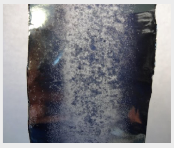
Corroded metalized film
MF-cap failure modes and failure mechanisms
Capacitors could fail due to various factors like design errors, manufacturing defects, material wear out, operating temperature, voltage, current, humidity, mechanical stress and inappropriate use beyond the scope of the specification.
For example, “Design errors” such as thin dielectric film, small insulation distance, too thick or thin metalized electrode layers, improper conductor current allowance settings, “Process defects” such as poor mechanical tension control during film winding, poor drying of capacitor elements, poor encapsulation, improper drying or encapsulation of capacitor elements, “Environmental factors” such as high voltage, electromagnetic interference (EMI), lightning, high temperature and high humidity environments, etc.
However, failures are rarely caused by a single factor, and it is common for multiple factors to cause various failure modes. In other words, a failure has a root cause that consists of multiple factors. For example, if the tension is not properly controlled during film winding, an air gap would remain between the film layers. Then SH events occurs in this air gap, excessive Joule heat is generated, severely damaging the deposition electrode, resulting in reduced capacitance or a short circuit.
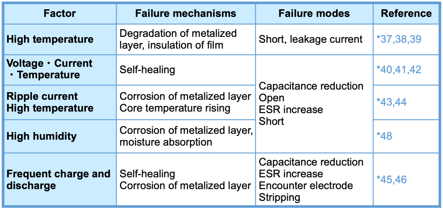
Table 4 gives a systematical summary of the failure factors, mechanisms, and modes of MF-cap. As with any other capacitors, t environmental and electrical factors have a significant impact on the failure and life of MF-cap, though. The most important reliability feature of MF-cap is their self-healing capability and the self-healing determines the mode of failure. If SH performance works properly, MF-cap is a highly reliable device that operates stably with an expected lifetime of over 100,000 hours; if SH does not function, it will lead to failures such as short circuits. Therefore, in order to use MF-cap safely, it is necessary to mitigate as much as possible the factors that may cause failures.
*37 Flicker, J., et al., IEEE 39th Photovoltaic Specialists Conference: pp. 3340-3342. June 2013. [7]
*38 Li, H., et al., Microelectronics Reliability Vol. 55 No. 12 (2015): pp. 2721-2726. [10]
*39 Mach, P., et al., 38th International Spring Seminar on Electronics Technology: pp. 272-276. May 2015. [11]
*40 A. Yializis, et.al., IEEE Int. Symp. on Electrical Insulation, Boston, MA (1980). [6]
*41 Schneuwly, A., et al., Materials Science & Engineering B Vol. 55 No. 3 (1998): pp. 210-220. [8]
*42 Emel’yanov, O., Technical Physics Vol. 56 No. 11 (2011): pp. 1685-1688. [9]
*43 Makdessi, M., et al., IEEE Transactions on Power Electronics Vol. 30 No. 5 (2015): pp. 2435-2444. [12]
*44 El-Husseini, et al., Journal of Physics D: Applied Physics Vol. 36 No. 18 (2003): pp. 2295-2303.[13]
*45 Lin, F., et al., Conference on Electrical Insulation and Dielectric Phenomena, Annual Report Vol. 2 (2000): pp. 592-595. [15]
*46 Borghetti, A. et al., IEEE Transactions on Power Delivery Vol. 10 No. 1 (1995): pp. 556-561 [16]
*47 Li H., Lewin P. et al., IEEE International Conference on Dielectrics: pp. 804-807.July 2016. [43]
*48 Brown R. W., IEEE Transactions on Device and Materials Reliability Vol. 6 No. 2 (2006): pp. 326-333. [17]
Gaps between dielectric film layers (air gaps) are one of major factors that inhibits normal SH events. Factors that cause air gaps include insufficient adhesion between film layers when the film is wound, and wrinkles in the film itself. (Fig. 12)

Image of MF-cap element eroded by heat generation due to frequent and repetition of SH
If the electric field in the dielectric film is higher than the dielectric breakdown strength of the air or gas in the air gap, local dielectric breakdown occurs in the vicinity of the air gap. The breakdown energy ionizes the air or gas in the air gap. This is known as partial discharge or corona. This discharge generates a small localized electrical arc that locally vaporizes the metalized electrode. If there are many large air gaps between layers of film, evaporation of the metalized electrode occurs frequently, resulting in a rapid decrease in capacitance. In segmental deposition electrodes, electrical discharges can also propagate from non-metalized areas separating the electrodes, causing significant capacitance reduction and insulation degradation.
This air gap could be improved by introducing high-performance film winding equipment that can flexibly handle different film types and thicknesses and by increasing the control level of winding speed and tension. It could also be improved by winding the film as tightly as possible and by heating the wound film capacitor elements to ensure proper heat shrinkage and tight film-to-film bonding*49. Some high-voltage film capacitors are impregnated with oil or epoxy (or other non-swelling, low viscosity, low surface tension, high oxygen content liquid*50) at the time of winding to prevent air gaps.
*49 D. Shaw, et al., “A Changing Capacitor Technology - Failure Mechanisms and Design Innovations," IEEE Transactions on Electrical Insulation, vol. 16, no. 5, pp. 399-413, 1981. [76]
*50 F. Lin, et al., “On the failure mechanism of metallized polypropylene pulse capacitors," in Conference on Electrical Insulation and Dielectric Phenomena, 2000, 2000, pp. 592-595. [77]
Failures of MLCC
MLCC also could either suffer from degradation or catastrophic failure.
Degradation failure of MLCC is a change over time in capacitance (capacitance decrease), also commonly referred to as aging. The aging commonly is observed in EIA Class II and III (X7R, X5R, etc.) high-k MLCC. However, in most cases, the capacitance of an MLCC is known to recover by heating above Curie temperature for several hours*51. The aging is due to changes in the dielectric’s crystal structure with temperature and time.
*51 D. Donahoe, et al., “Moisture induced degradation of multilayer ceramic capacitors," Microelectronics and Reliability, vol. 46, no. 2-4, pp. 400-408, Feb. 2006. [81]
Catastrophic failure of MLCC is primarily dielectric breakdown. Catastrophic failure in ceramic capacitors tend to result in crack propagation through the dielectric ceramic during breakdown *52. There are three modes of dielectric breakdown in ceramic capacitors, intrinsic, thermal, and ionization.
*52 J. Ho, et al., “Historical introduction to capacitor technology," IEEE Electrical Insulation Magazine, vol. 26, no. 1, pp. 20-25, 2010. [61]
[Intrinsic breakdown]The most common cause of failure is intrinsic breakdown. This breakdown failure occurs when the applied voltage is larger than the ceramic material can withstand. The intrinsic strength of the ceramic depends on the ceramic porosity, grain size, conductive impurities, manufacturing methods, past applied voltage value, applied AC voltage frequency, voltage ramp rate*53, and any mechanical defects. Ceramics tend to crack under high fields. This cracking is facilitated by any strain due to clamping or electrode connections to the ceramic. Because ceramics are brittle materials, any small cracking quickly grows and propagates throughout the entire dielectric.
*53 A. L. Young, et al., “Mechanical vs. electrical failure mechanisms in high voltage, high energy density multilayer ceramic capacitors," Journal of Materials Science, vol. 42, no. 14, pp. 5613-5619, Apr. 2007. [93]
[Thermal breakdown]Thermal breakdown can lead to catastrophic failure of the MLCC dielectric. In this failure mode, a chemical reduction reaction occurs in a localized portion of the dielectric. Since the reduced dielectric has a higher conductivity and large current easily flow through dielectric, the temperature rises rapidly due to Joule heat and further reduction of the dielectric, eventually causing the dielectric to melt and the capacitor to short*54, or delamination and cracking due to the difference in coefficient of thermal expansion (CTE) between the dielectric and the electrode and the current is interrupted *55 .
*54 W. Bahn and R. Newnham, “Microdefects in batio3 capacitors," Materials Research Bulletin, vol. 21, no. 9, pp. 1073-1082, 1986. [95]
*55 J. Yamamatsu, et al., “Reliability of multilayer ceramic capacitors with nickel electrodes," Journal of Power Sources, vol. 60, pp. 199-203, 1996. [96]
[Ionization breakdown]MLCC can also fail due to ionization breakdown. In this process, an electric current flows due to Poole-Frenkel emission*56. Due to the porosity and other structural features of the ceramic, the localized electric field inside the dielectric is much larger than the normal electric field. This enhanced electric field allows electrons to have sufficient energy to knock multiple electrons into the conduction band like an avalanche *57 *58. This results in dielectric breakdown at low applied voltages. The dielectric strength of MLCC is known to be highly dependent on the porosity and defect density (grain boundaries, voids, etc.) of the ceramic.
*56 E. Loh, “A model of dc leakage in ceramic capacitors," Journal of Applied Physics, vol. 53, no. 9, pp. 6229{6235, 1982. [97]
*57 J. M. Herbert, “Production of ceramic material," US Patent 3,041,189, Tech. Rep.,1962. [85]
*58 B. Rawal and N. Chan, “Conduction and failure mechanisms in barium titanate based ceramics under highly accelerated conditions," in Proceedings of the 34th Electronic Components Conference, 1984, pp. 184-188. [99]

Editorial supervision/Kazuyuki Iida
General Advisor, AIC tech Inc.
Born in the Tokyo area in 1956
M.S. of Sc, Sophia University, Tokyo, Japan. 1982
Over 35 years experience with knowledge on capacitor technology, i.e. R&D for high-performance capacitor and its materials, marketing activities at Hitachi Chemical Co, Ltd. and Hitachi AIC Inc. and Contributed articles on capacitors to public relations magazines, trade journals, and various handbooks.
Instructor of capacitor technology at the Technical Training Institute of Hitachi, Ltd. from 2005 to 2015.
General advisor to AIC tech Inc. from 2020.
- "Tantalum Electrolytic Capacitor"
The Electrochemical Society of Japan (ed.) Maruzen Handbook of Electrochemistry, 5th Edition, Chapter 15, Capacitors, Section 15.2.4 b (1998) - "Development Trend and Material Technology of Tantalum-Niobium Capacitors"
Technical Information Association of Japan Seminar June 2008 - Lead-Free Surface Mount Film Capacitors MMX-EC, MML-EC Series
Hitachi Chemical Technical ReportNo. 48. Product Introduction 2007 - "Film Capacitors for Electronic Devices"
Maruzen Capacitor Handbook, 5th Edition, Chapter 5, Film Capacitors, Section 5.2 (2009). - "Film capacitor MLC series for new energy"
Shinkobe Electric Co., Ltd. Shinkobe Technical Report Np. 22 (2012).
PDF Download
